

Kaos came with an electrical system that I wanted to completely replace. After lot of design and prototyping, version 1 of the new system has been in place for 6 months and is working extremely well.
The Existing System
The original system was a pretty typical setup that needed some updates. There were OK groups of batteries for the main engine start bank, generator, and thruster. They were being charged in weird ways, and the thruster batteries were as far as possible from the actual thruster, but they worked reasonably well.
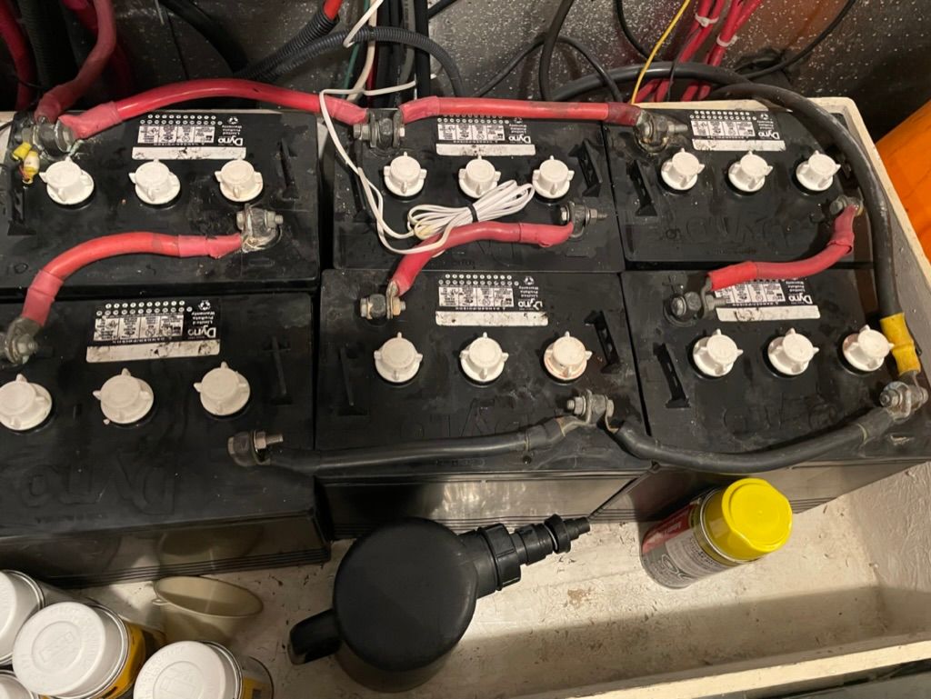
There was a house bank and an inverter bank, both using the same style of GC2 6 volt flooded batteries. The house bank was 6x of these located in the engine room, and were responsible for all DC 12 volt loads - lights, pumps, instruments, and also some heavy loads including the windlass and dinghy davit. The inverter bank was in the lazarette and consisted of 8x of the same GC2 6 volt batteries connected directly to a Magnum MS2812 inverter that powered all outlets throughout the boat, the refrigerator, and the microwave.
In total, I had the following capacity:
- House bank - 705 amp hours, 353 usable
- Inverter bank - 940 amp hours, 470 usable
Those are pretty typical numbers for this type of system, but really low for a boat this size, and definitely not the capacity I want for the future. The biggest problem with the existing system was age. The house batteries were from 2015 and well past their usable lifetime.
Within the first week of owning the boat, I determined the house bank was actually worse off than originally thought. It couldn't even last a 2 hour inaugural cruise from Anacortes to Friday Harbor without dipping below 11 volts and causing issues. I ended up having to run the generator the whole time underway - not a long term plan.
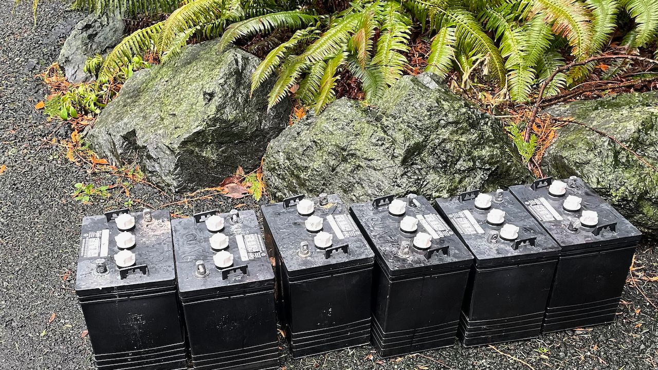
Old and new flooded batteries.
While in Friday Harbor, I ended up having to replace all 6 of the house batteries in order to continue using the boat reliably for the next couple of months while I finished the design.
Even with new batteries, this sort of configuration is not optimal - having the house and inverter banks separated is a throwback to when boats had limited or no inverter power, and one was added. It adds inefficiencies and more complexity. Kaos also had an automatic charging relay (ACR) that was installed to combine the house and inverter bank which allowed for slightly better balancing, but really confusing charging results.
With this setup, my average generator run time was between 4-5 hours per day, sometimes more depending on what was going on.
I also had reverse engineered the AC panel and shore power connections and found some concerning things. Open grounds, weird wiring for the 50 amp 240 volt input connector, etc. After a lot of review, I wanted to simplify the way the panel was setup as much as possible, and re-do the wiring for the shore power side of the world to make sure it was more reliable and safe.
New System Goals
The main goals with the new system were:
- Single bank for inverter / house loads
- More amp hour capacity
- Shorter generator run time / faster charging
- More inverter power / all AC loads on inverter (stretch goal)
- Better visibility and control
48 Volt Discovery
One of the most interesting things I investigated was using 48 volt batteries as the core of the system. I had been watching the market and various products that had become available since my previous boat Rendezvous LiFePO4 power system, and had liked the idea of having a more dense, efficient battery bank at a higher voltage.
I spent a lot of time on forums, talking to experts, and even deeper dives with boaters that already have 48 volt systems. This included folks like Peter Kennedy at PKYS, a Victron expert and a very accomplished ABYC Marine Electrician, and boater David de Regt on Highwind who had installed a 48 volt system aboard his boat, and a handful of others.
What I found was a good core of products that work with 48 volt systems, but key pieces that are a challenge in some way. For example, there are only a handful of 48 volt alternators and the cheapest ones I found were in the $2000-3000 range.
Other challenges included converting 48 volts to 12 volts, which I needed for my existing DC system. Finding solutions to do this was the biggest challenge in the design, and proved to be almost impossible without relying on brand new technology that was even too bleeding edge for me, or using other solutions which weren't meant to be used for this sort of system.
Finding batteries was a bit of a challenge as well. None of the mainline marine vendors produce a 48 volt battery, which means either combining a couple of 24 volt batteries, or choosing less mainstream options.
Finally, there are challenges with ABYC and other regulations around 48 volts, although some have improved in recent months. Many of the regulations end their approvals at 48 volts, which was an issue for any system since the charging rates for a 48 volt system are actually higher.
Ultimately, I decided that going for a 48 volt system was too risky for Kaos at this point in time. Maybe in the future!
24 Volt System
I settled on a basic design around a 24 volt battery bank with 24 volt inverters. Using 24 volts instead of 12 creates a problem, and solves another.
The problem it creates is that the rest of the boat's DC system is still 12 volts, and I'm not changing all of that. There are some solutions to that, which are covered in my design further below.
The problem this solves is the cabling and charging challenges found with 12 volt LiFePO4 systems of any decent size. This is a common issue I see in designs particularly around cabling. A common cabling size used for big battery banks and inverters is 4/0 AWG. ABYC says that a single conductor, used in an engine room, at 105 degrees C, not bundled, sheathed, or in conduit has a max ampacity of 378.3 amps. That same size wire in a group of three, sheathed, bundled, or in conduit drops to 264.8 amps.
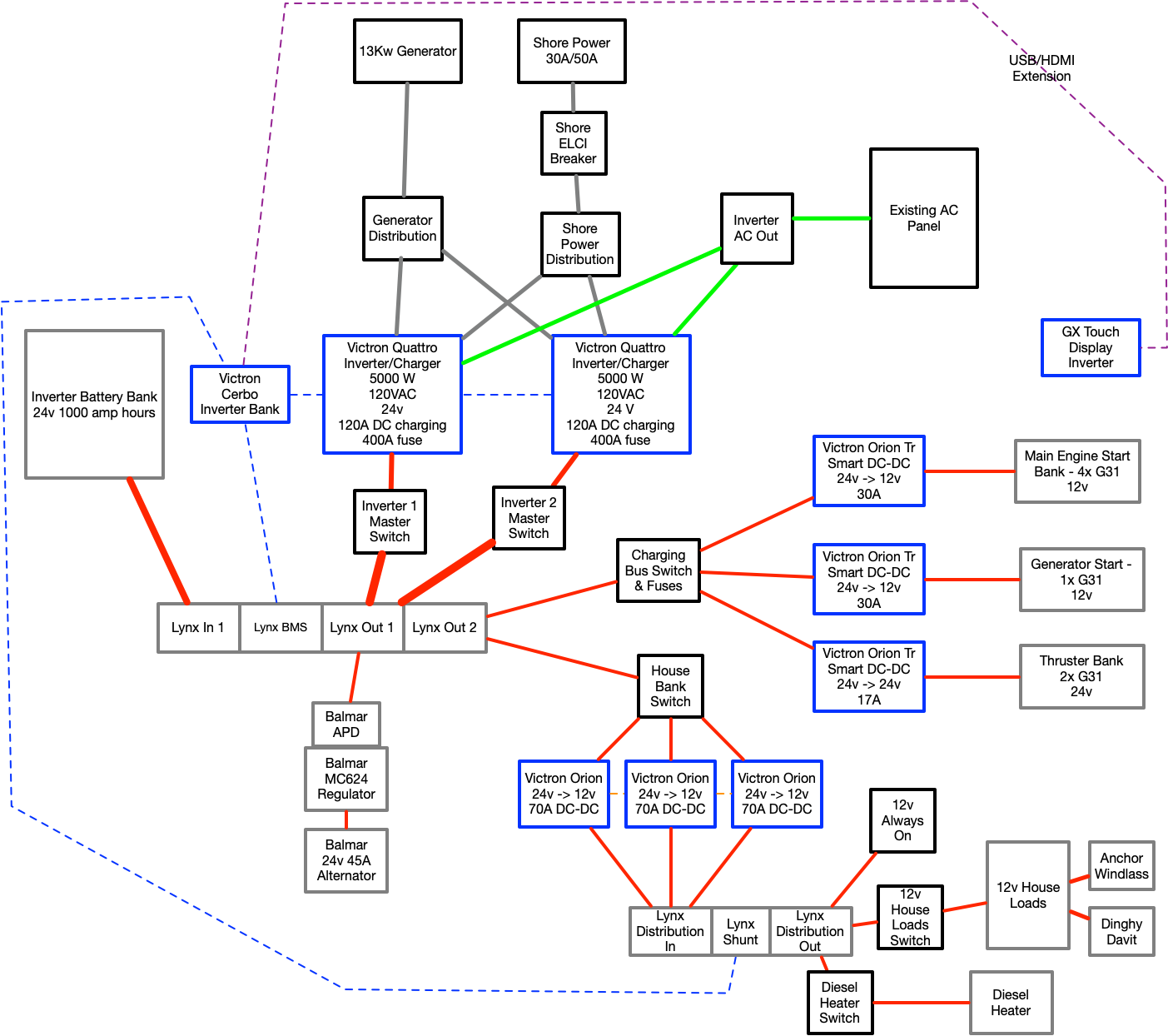
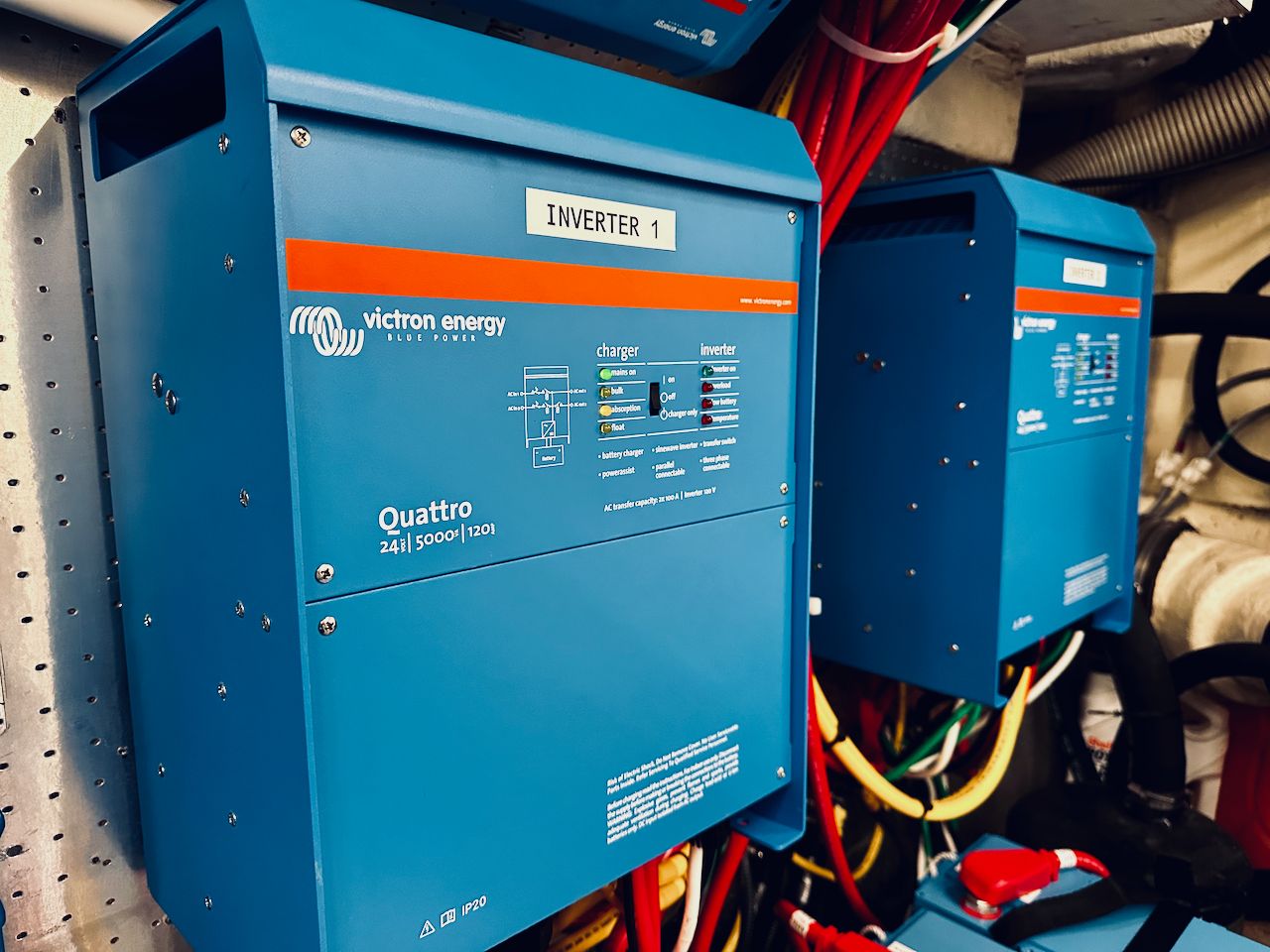
A common design using dual Victron Quattro inverters is a great way to illustrate the challenges here.
- 12 volt Victron Quattro 5000W 120V AC inverter - max charge per unit - 200 amps. 2x units = 400 amps.
- 24 volt Victron Quattro 5000W 120V AC inverter - max charge per unit - 120 amps. 2x units = 240 amps.
Depending on how you wire the 12 volt system, you could end up needing two 4/0 AWG conductors to carry 400 amps safely, and if you do that, they could technically need to be individually fused - again, depending on the design. If they are individually fused, you could also need to somehow disable the inverter/link/wiring if one fuse fails, otherwise you'd have the full load on one wire.
This is just an example with an inverter - if you throw alternators or other charging devices in the mix, you could end up with a lot more to deal with, and trying to do that at 12 volts is becoming more and more challenging.
24 volts just makes a lot more sense from the cabling and charging world, and there are a lot of products and solutions available for this voltage.
Vendor Choice
While I have been a Victron convert for the last couple of boats (Rendezvous & Grace), I try to stay current on what all of the other vendors in the space are doing. I had worked on many MasterVolt systems in the distant past, and really like the quality of their equipment, but they have a gap with monitoring and management compared to Victron. Outback was the other vendor I spent a lot of time reviewing this time around, and have loved their rock-solid inverters for years. They also have pretty terrible management, and were missing other features that I wanted around redundancy, so they weren't a choice.
Most of my experience with customers and my own boats in the last 5 years has been around Victron. They have a lot of great features, but they design things like engineers, for engineers. That's not necessarily a bad thing, but it can mean a lot of work to figure out moderately complex configurations, and unclear documentation about how things work.
Nevertheless, I had become addicted to features like Power Assist, the online VRM portal, and the lovely GX-series screens and data that you can see about your power system. So Victron it was....
Drop-In vs. Normal LiFePO4
On Rendezvous, I used Battle Born GC2 batteries, a drop-in LiFePO4 battery. On Grace, I used Victron's LiFePO4 batteries. The difference between these types of batteries has been a topic of discussion before on my site, as well as many other places, and have their pros and cons.
I really liked the simplicity that the Battle Born batteries provided, but there was little visibility into what was going on with each battery. The form factors are also pretty limited - G31, GC2, and 8D - and I wanted a bit more choice.
A lot of the traditional LiFePO4 batteries from Victron, Mastervolt, and others are not as energy dense as I would like, and are really expensive.
However, around the beginning of 2022, Victron released a new "-a" battery that matched my needs, and with some serious discounts, they were comparable to drop-in pricing. Additionally, they were a better form factor and weight, so I was sold on using these for my design.
Design
The final design took a while to settle on both during the design phase, and during implementation. I'm a huge fan of iterative design, and always prefer refining a design or a system over time to make sure it is as efficient and effective as possible. In the case of this system, I made a few changes while installing things after being able to test some of the configurations in the real world.
I'll try to break apart the major components of the system below and describe the installation and design.
House Batteries
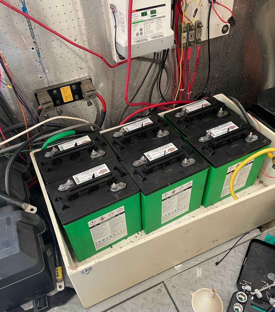
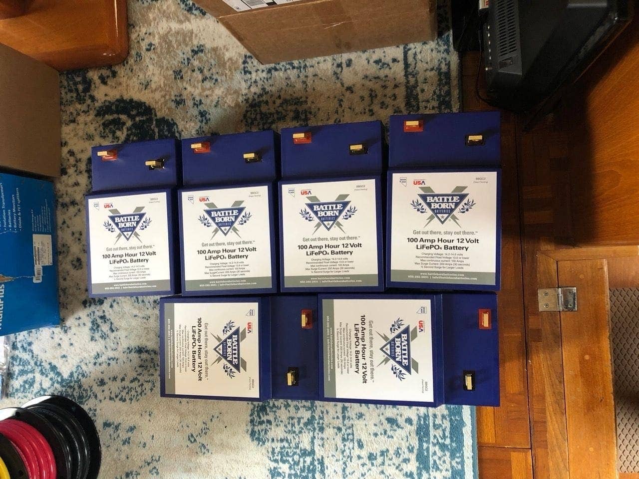
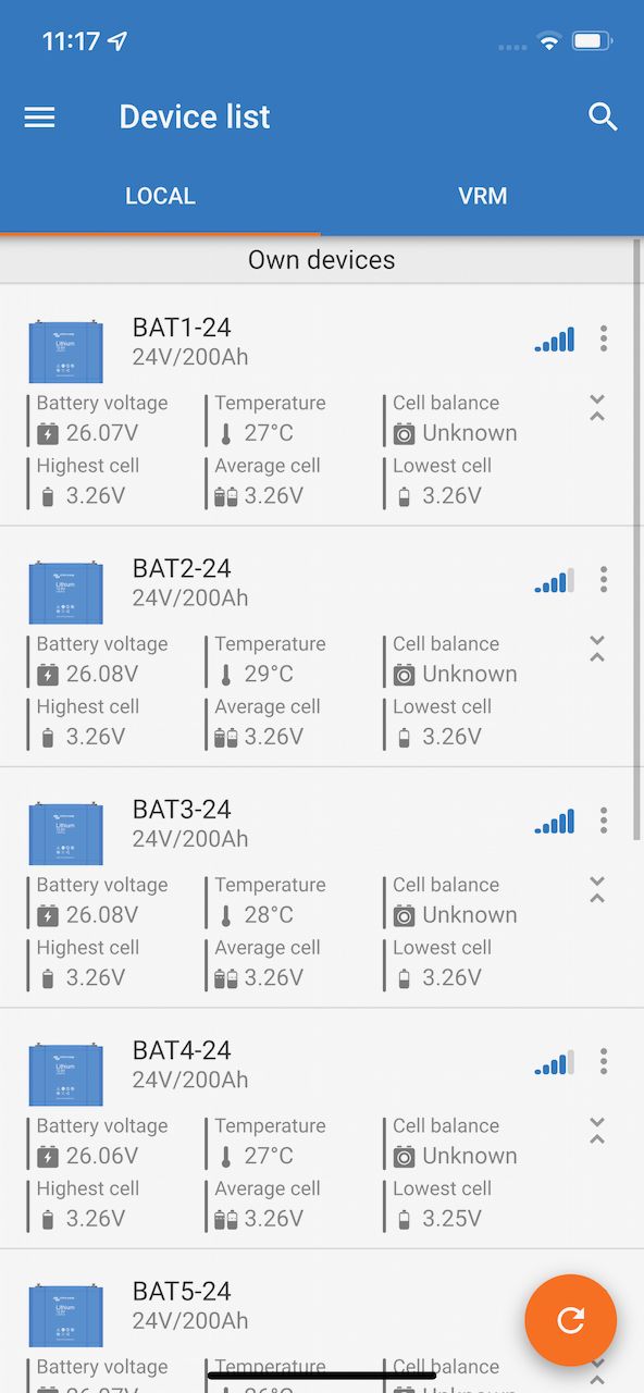
Victron released a newer version of their 24 volt, 200 amp hour LiFePO4 battery around the time I was doing my installation. They are the LFP-Smart 25.6/200-a model and are quite a bit nicer than the previous versions.
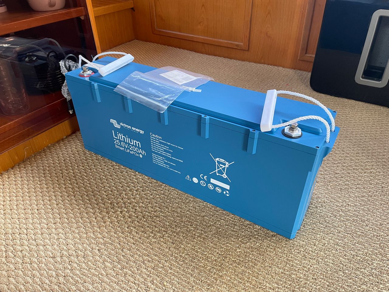
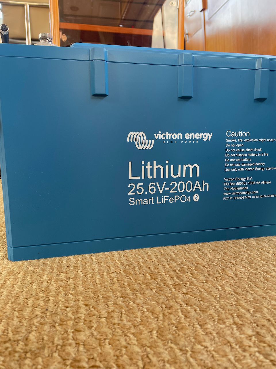
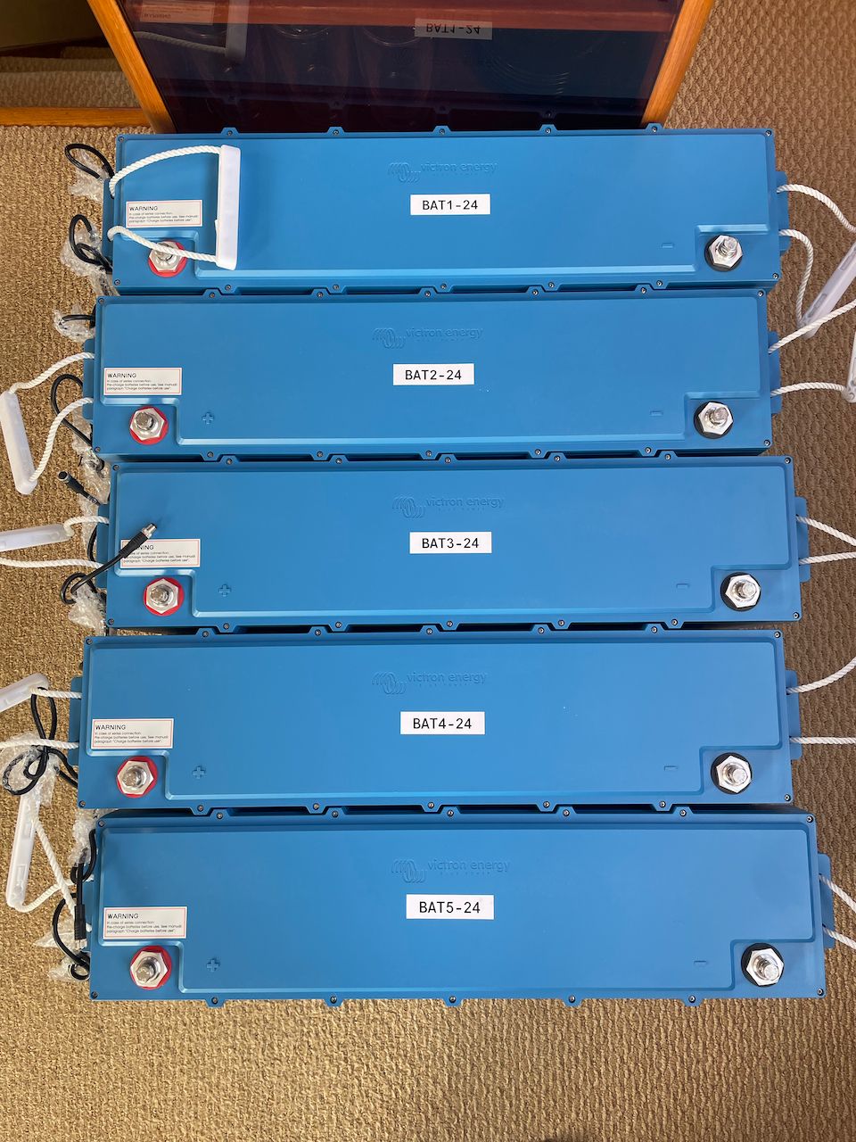
Victron LFP-Smart 25.6/200-a LiFePO4 batteries
They are smaller than the previous version, lighter, and have a more thoughtful form factor (in my opinion). I ended up getting 5x of these for a total of 1000 amp hours at 24 volts. They are well built, have really nice handles, big bolts and connection points, and built in cables to connecto to the BMS.
The existing system was 470 usable amp hours at 12 volts, or 823 usable amp hours if you added in the DC bank, although I never got that out of the system. If you convert the new system to 12 volts, it would be 2000 amp hours which is 1177 more amp hours of capacity. Definitely an upgrade!
I was able to install the new batteries in the engine room in roughly the same space as the original 6x GC2 batteries, although oriented slightly a different way. That replaces the 6x GC2 house bank and the 8x GC2 batteries in the lazarette that were used by the old inverter.
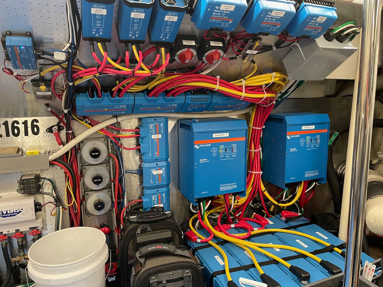
Inverter / Chargers
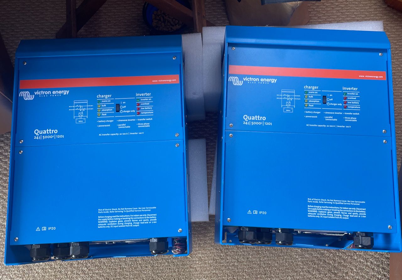
I chose Victron's Quattro inverters for the design because of their general charging and overall capacity, and ability to deal with two AC input sources.
The original inverter was only 3000W, and I knew that I would need a lot more capacity if all AC loads were going to move to inverter. Charging was also a big reason to select these inverters as each one is capable of producing 120 amps of 24v DC. Combining them would provide a maximum of 240 amps of synchronized DC charging to the 1000 amp hour bank.
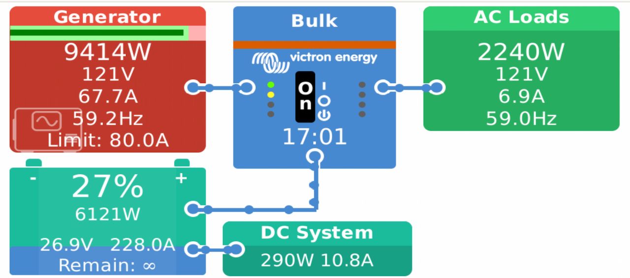
At that charging rate, it would require about 50 amps of AC power. My generator is a 13kW Kohler 120 volt AC model and a maximum of 100 amps of AC. I don't want to run it at more than 80% load or 80 amps of AC, so around 50 amps being dedicated to charging is pretty good. That leaves 20-30 amps of AC power for other loads such as the water maker, and the 5-10 amps of normal AC usage.
Parallel vs Split Phase Inverters
This was one of the biggest experimentation areas for the whole design. The boat came with a 50 amp shore power inlet wired where each phase went to a different part of the panel, but was not wired correctly. Since the boat only has 120 volt AC appliances throughout, and there's no real plan to change that to 240 volt in the short term, I was open to different setups.
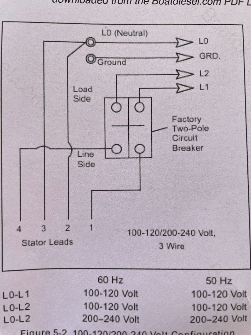
The other wild card was the 13kW Kohler generator. It came wired as a 120 volt AC system, but I had hopes that I could convert it to 240 volt AC given that I knew of two other people with the same unit who had that configuration already. Unfortunately, after a week of experimentation, I was not able to get it to work correctly at 240 volts, and even had a thread on Trawler Forum looking for advice.
I was trying to get both shore power and generator to provide 240 volt AC power with two phases. That would allow me to maintain two separate AC sections on the main panel, each having a phase of power providing 50 amps of 120 volts. This would mean that the inverters would be configured in split phase mode, with each one handling one phase of the incoming power, and capable of outputting both 120 and 240 volts if I wanted.
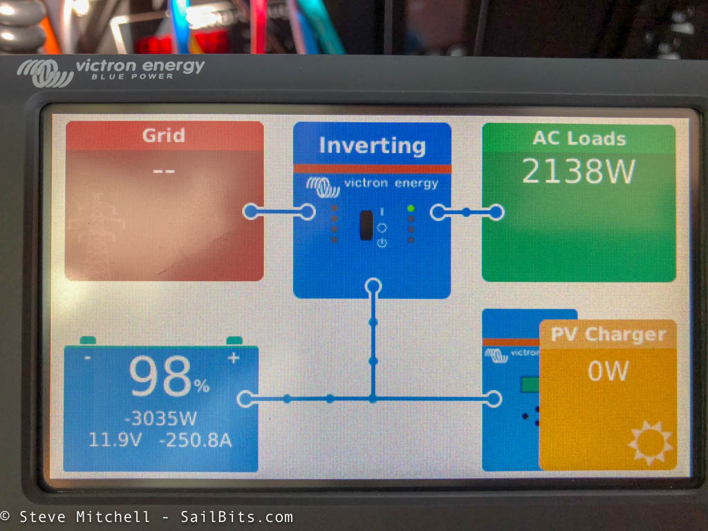
Unfortunately, due to the generator being stuck at 120 volts, I couldn't do that. But it actually worked out better than I could have hoped.
One of my goals was to put as much as possible on inverted power so that there was less messing around turning on/off the generator and circuit breakers when someone needed to run some appliance. In addition, I wanted to make it as simple as possible to run it and not have to worry about balancing phases.
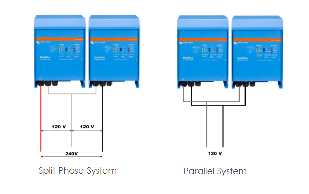
As a result, I configured the inverters to be in parallel which allows for a few benefits:
- Simpler system - less complexity than having multiple phases, breakers, etc.
- Single AC output to the panel - less work to balance phases, all inverter power is available to the entire panel and not split
There is one downside, and that has to do with utilizing the maximum amount of shore power. Originally with 50 amp 240v coming into the boat, I had the ability to split the various AC loads across two phases - essentially two banks of 120 volts each at 50 amps. With this new configuration, I will only be using one phase of the two, which means I can only get 50 amps total out of shore power.
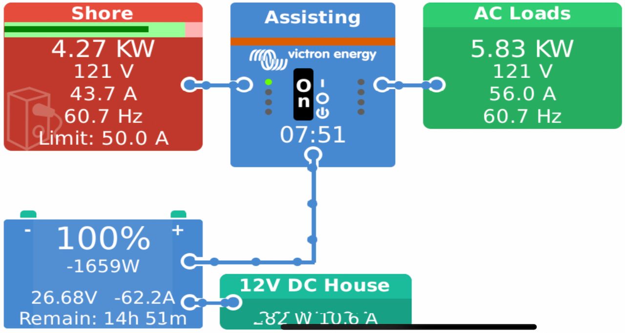
I was initially worried with this limitation, as I would like to have as much power available as possible. However, after 6 months of using the setup, I have no regrets and have had zero issues. Victron's Power Assist feature has stepped in wherever I've needed more than 50 amps of power, which has been rare. During normal use, I rarely ever need a full 50 amps of power continuously,
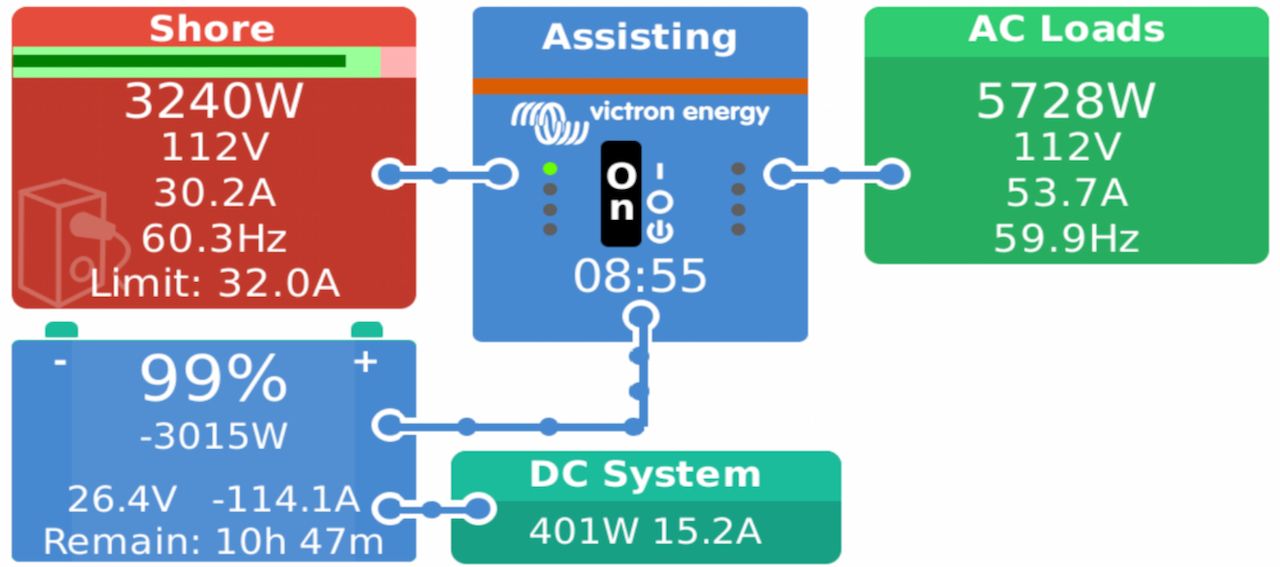
I've even used the system with 30 amps of shore power in a couple of places. It's worked just as you would expect, providing more power - here around 54 amps - while needed, and then charging the batteries back up later.
Everything on Inverter
As a result of this setup, I chose to put everything on the inverter which has been wonderful from a usability perspective. We can run anything and everything all of the time, regardless of whether we have shore power or generator power.
That makes a big difference for folks who don't know how a boat works - they don't need to ask to use something - everything just works. The downside is that it does require a bit more thought around what you leave on all of the time. I have big block heaters for my engines which I've left on once or twice, only to notice them a few hours later. I'll take the inconvenience for the overall simplicity of the entire system.
Wiring
With the new design, I had some wiring challenges with the AC power side of things. First, the shore power inlet is amidships at the pilot house door on the starboard side. The AC panel is right there as well, but I wanted all of the AC power to go through the inverters to take advantage of Power Assist and all of the other monitoring capabilities. This meant that I needed a new cable from the shore power inlet to where the inverters were being installed in the engine room.
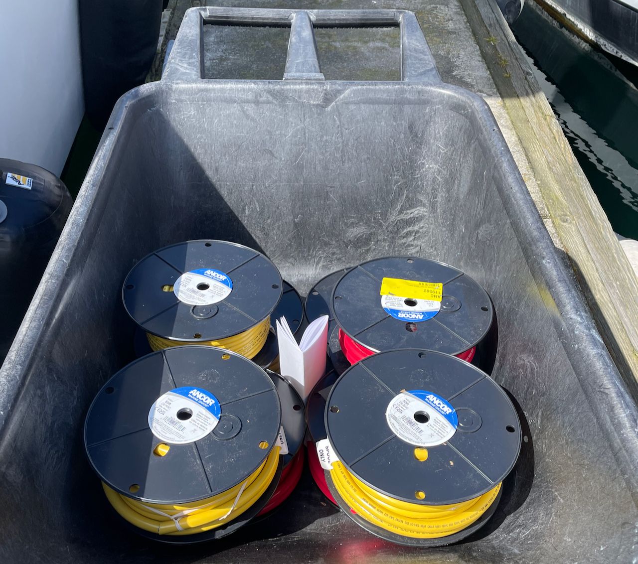
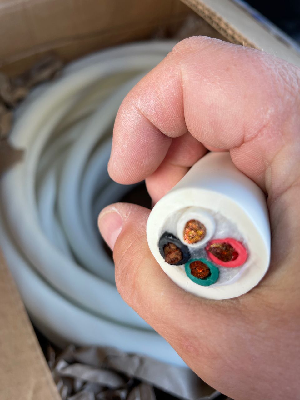
I also needed a new set of wires from the inverters back up to the AC panel, as the previous inverter was only powering a small part of the AC panel, and I was moving everything over to run through the inverters. I chose some beefy 6 AWG wires with four conductors in them. I had to run it from the pilot house down the side of the boat and into the engine room. Thankfully Kaos has a cable tray the whole way, and it was pretty easy! That's a rarity based on previous boats and customer installs.
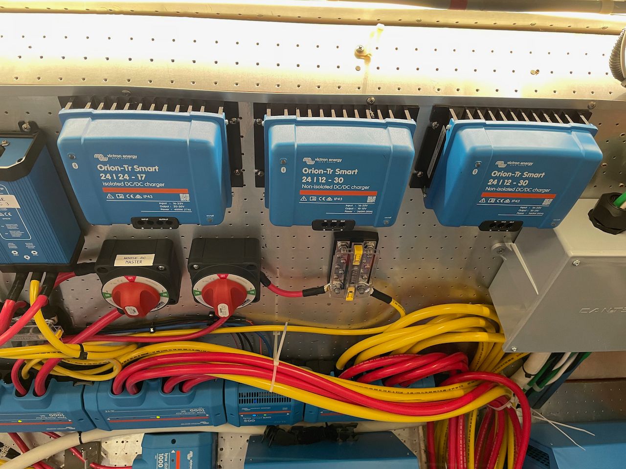
12 Volt DC System
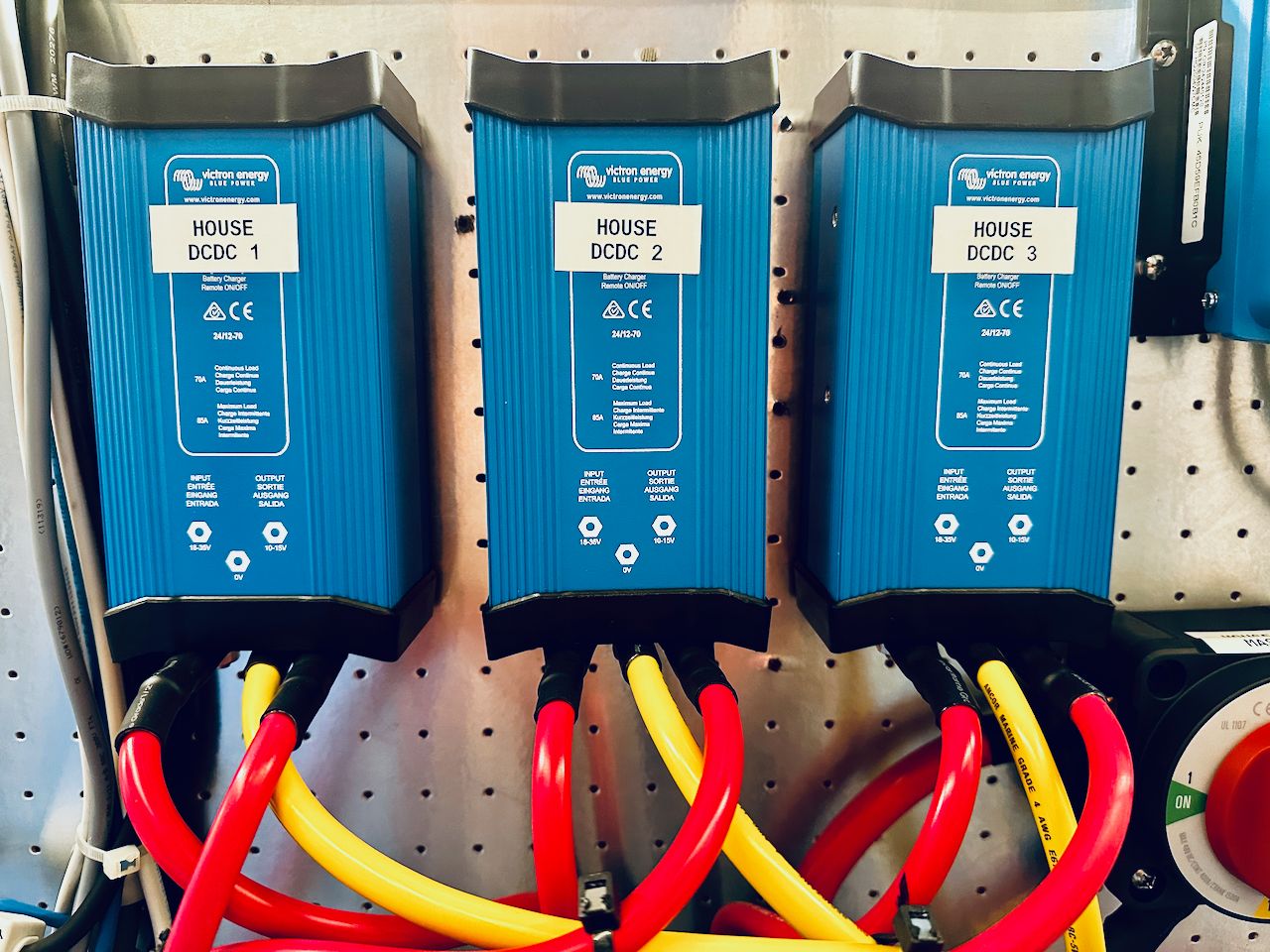
The entire DC system on Kaos is 12 volts, and I was not replacing or upgrading that as part of this project. I tried a number of different combinations of things over a 2 month period, and ended up settling on 3x Victron Orion DC-DC power supplies that convert 24 volts to 12 volts, and are each capable of 70 amps. That gives me a total of 210 amps of 12 volt power, which is more than double what I calculated my max usage was. It also provides some redundancy since I have 3 units in case of a failure.
These little boxes actually worked better than a dedicated AGM battery bank that had similar amperage numbers. While the batteries could last on their own without anything else powering them for a while, the voltage drop was significant with any sort of decent load. The Orion power supplies don't sag quite as much, and I was able to dial them up to 13 volts and get a consistent voltage out of them compared to a battery.
The one challenge is the 12 volt anchor windlass where in some situations, it draws an enormous amount when it is heavily loaded and causes a voltage sag. This causes some sensitive things to restart. The eventual plan is to upgrade the anchor windlass motor to 24 volt and connect it to the existing 24 volt thruster bank.
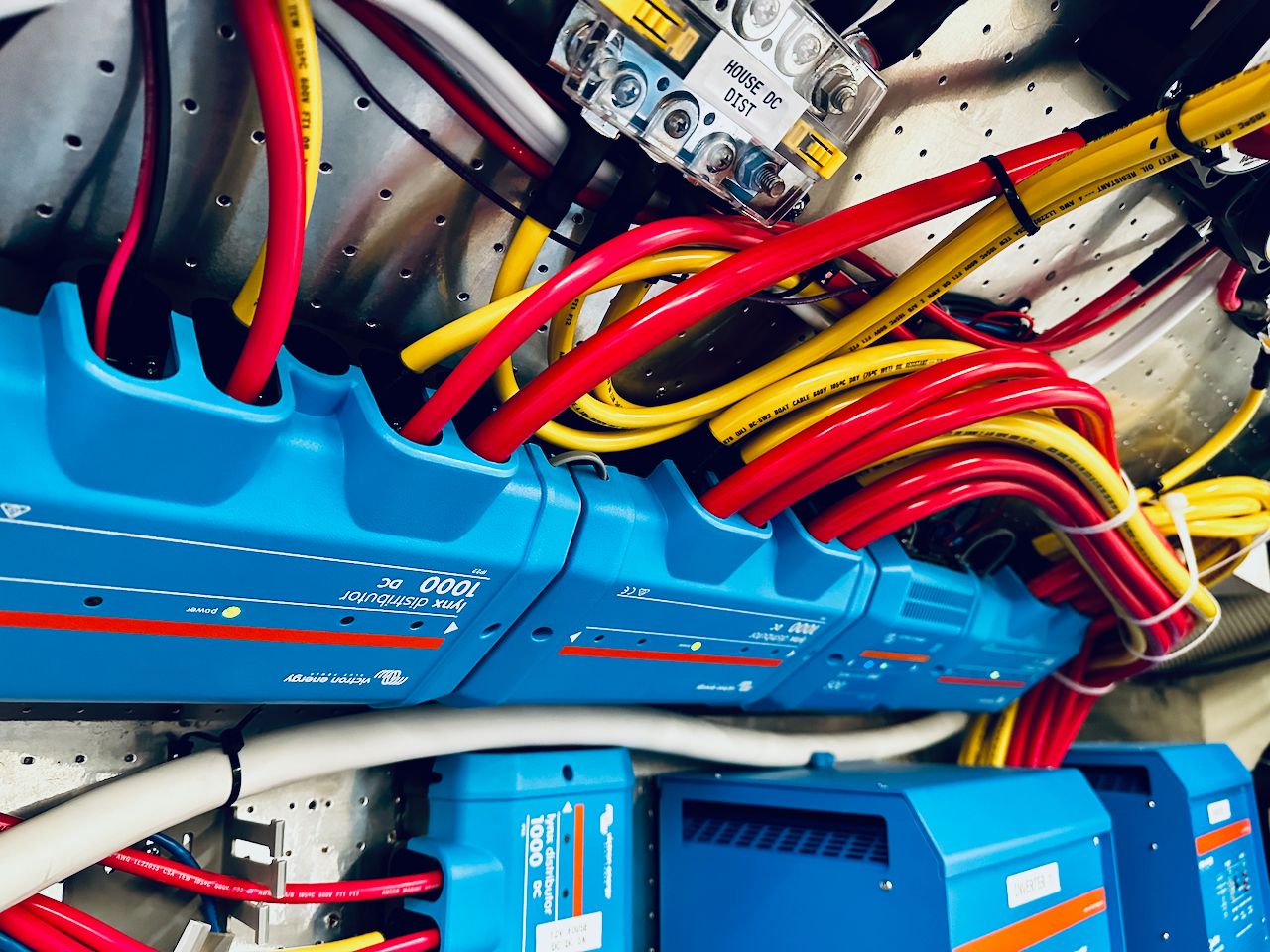
Lynx Distribution, Shunt and BMS
I had used the Lynx distribution system on a few other customer projects, but never on my own boat. I had also never used the BMS or Shunt products from the Lynx series.
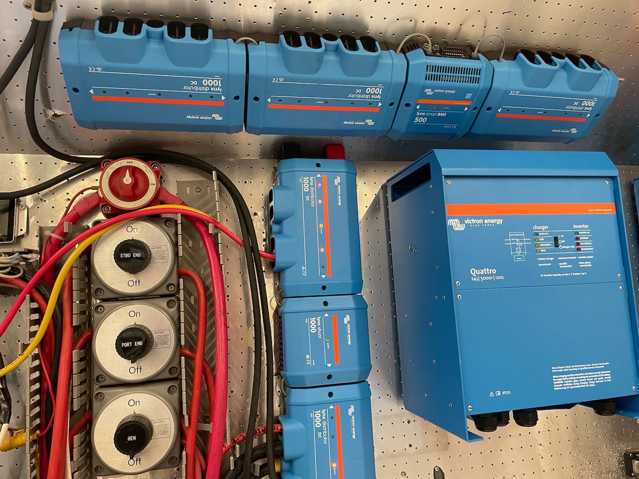
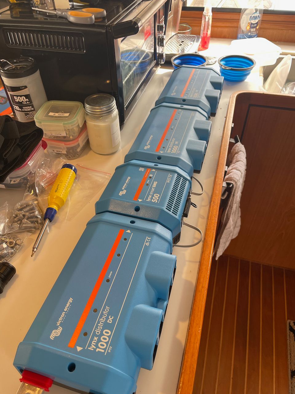
Lynx distributor and BMS
I chose the Lynx distributor for the battery and inverter connections. Each is fused and connected to the rest of the system so that any blown fuse causes an alert, and provides details on which fuse has an issue. I looked at BlueSeas and Marinco Pro Installer bus systems, but they would have ended up being bigger footprint-wise, and some of them had lower amperage ratings that didn't meet my design.
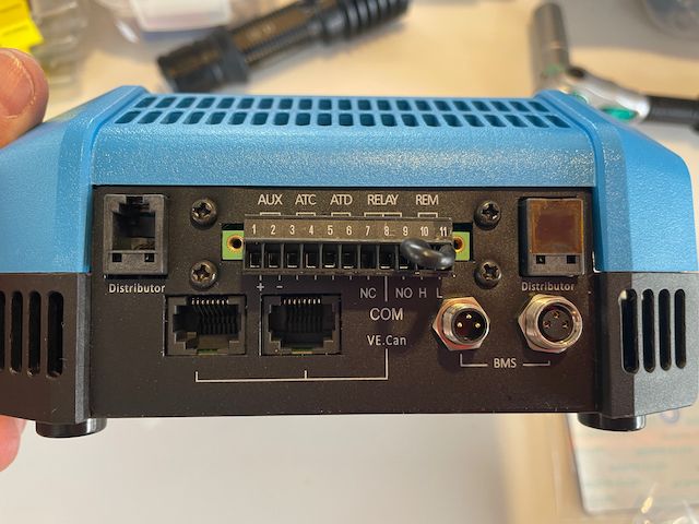
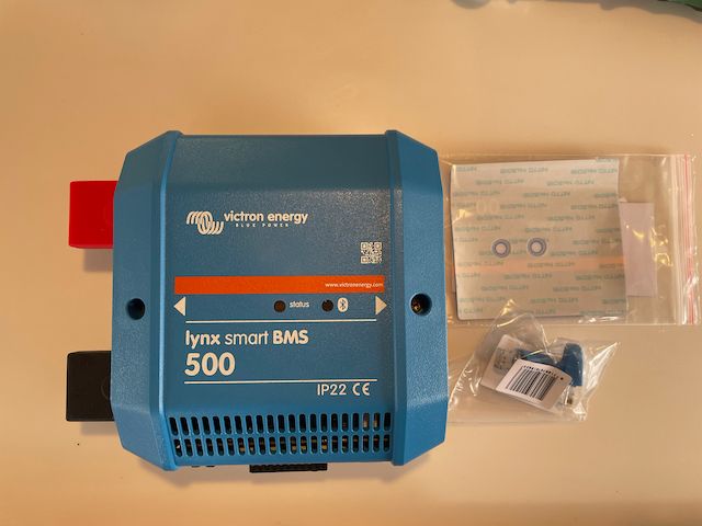
Lynx Smart BMS
I chose the Lynx Smart BMS after a lot of painstaking research. This is one of the challenges with Victron - they have too many choices for shunts and BMS's, and each of them have some big gaps that cause design issues or changes. The Lynx Smart BMS is probably their most advanced, and provides a lot of nice features. It has a dedicated connection for the distributors to read the fuse statuses, for the batteries to manage them, VE.Can to connect to the inverters and GX device, and individual connections to power the GX system.
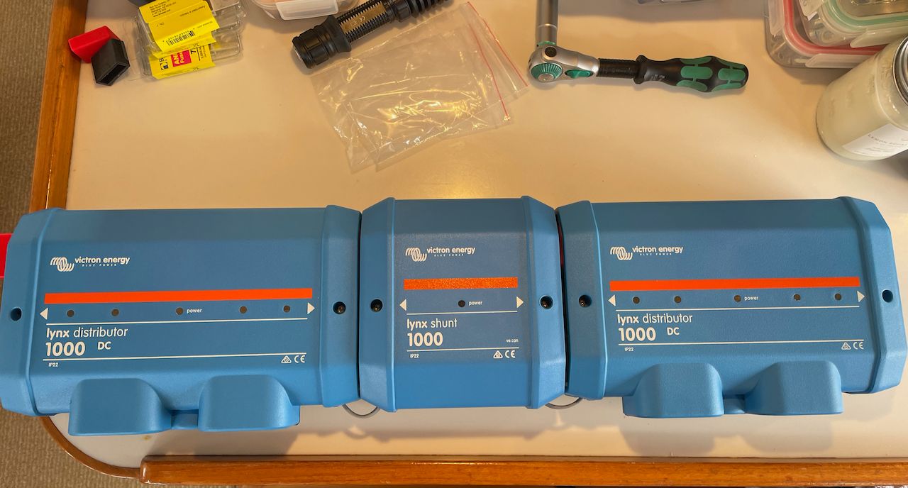
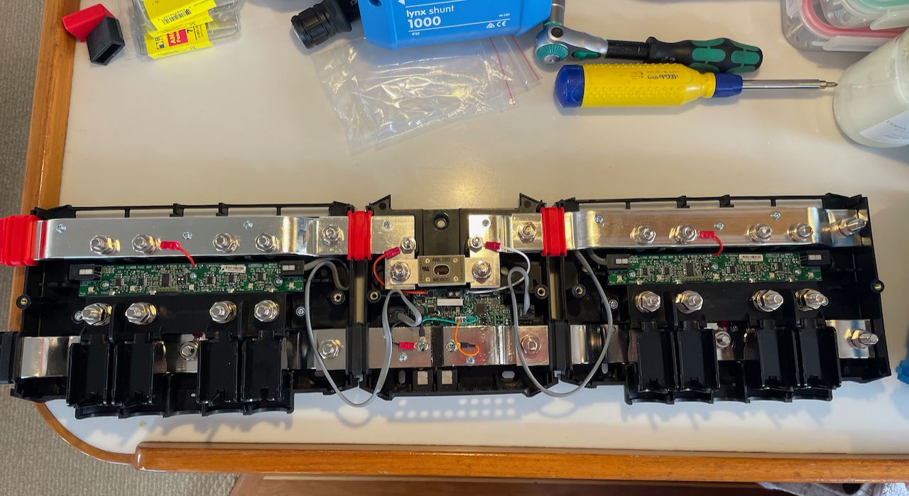
Lynx distributor and shunt for the 12 volt system
I also chose to use the Lynx distributor system and shunt for the existing 12 volt system. I used one side of the distributor for the three Orion DC-DC power supplies that run the 12 volt system and their input power. Three fuses on that side protect the power supplies.
The shunt is there so I can monitor the amount of power that the 12 volt system is using, although you can sort of already see that with the "DC System" statistic on the GX display. On the other distributor I have 2x 0/2 AWG cables going to the main DC panel in the pilot house, one going to the diesel heater, and one going to always on circuits in the engine room.
There are a lot of other features, and issues, with the Lynx Smart BMS, shunt, and distributors that could benefit from a dedicated article in the future. Even so, I have been very pleased with the clean install of the Lynx system, the shunt, BMS, and other protection pieces all built in, and how well it has worked so far.
Charging other battery banks
Just like Grace and Rendezvous, I chose to make charging other banks as reliable and simple as possible. I hate ACRs or other combiners because of what can go wrong with charging the wrong thing or the current flowing the wrong direction. They also do not work well with different battery charging profiles or chemistries, which I definitely have in this system:
- Main engine start battery bank - 4x group 31 "maintenance free sealed" flooded batteries.
- Thruster battery bank - 2x group 31 "maintenance free sealed" flooded batteries
- Generator start battery - 4D flooded battery
All of these batteries will be replaced in late 2022/early 2023 with group 31 AGM batteries from Lifeline, but weren't part of this budget / project.
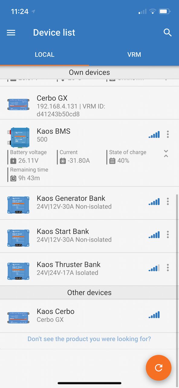
I chose various versions of the Orion-Tr Smart DC/DC chargers - one for each bank - which are supplied from the main 24 volt inverter bank. This guarantees that all three of those battery banks are always charged with the proper profile, that current only flows one way, and I can monitor them via the VictronConnect app. This is similar to what I did on Rendezvous, and provided a very reliable, hands off way to ensure other battery banks are always charged.
Alternator
Unlike the last two boats, I chose not to install high amperage alternators for a few reasons. First, I had lots of challenges with regulators and alternators being reliable all of the time with high outputs. It required a lot of attention and time, and although they did provide great charging underway, my setup with the dual Quattro inverter/chargers provided a much more efficient and predictable way of charging. Second, the Caterpillar 3208 engines in Kaos had limited space for alternators, although one was modified for a larger one. I didn't really want to mess around with additional modifications.
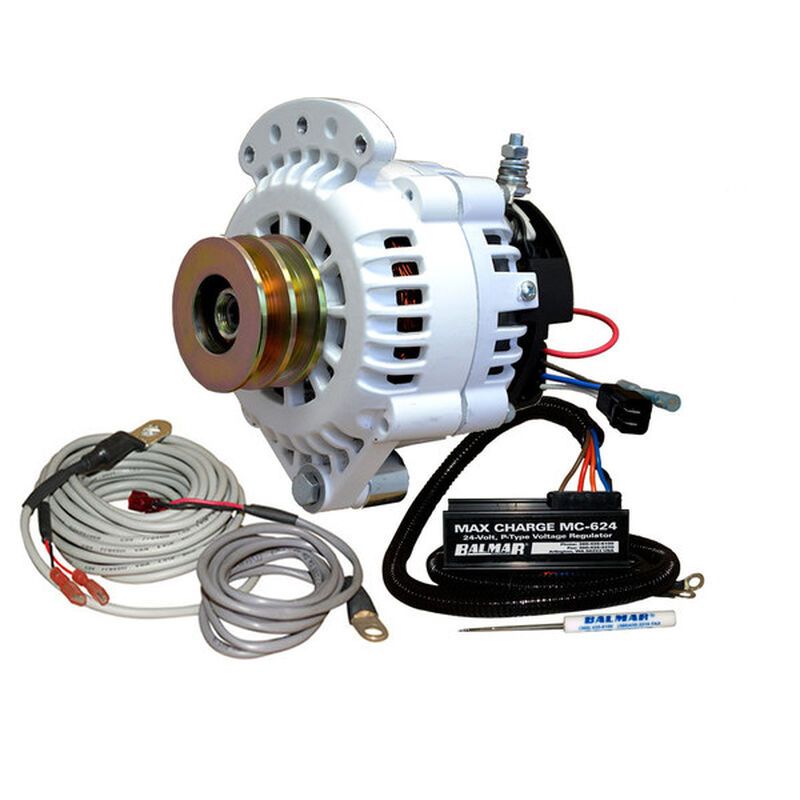
You may also notice that I am using a Balmar regulator and alternator instead of the Wakespeed systems I've used in the past. I did start with a Wakespeed WS-500 regulator in this system, and it was connected to the Lynx Smart BMS. Unfortunately, it did not end up working reliably, and I removed it. I ended up with a 45 amp 24 volt alternator paired with a Balmar MC-624 regulator and a Balmar alternator protection device.
This means I don't have a huge amount of underway charging, but it is enough that I don't end up discharging while underway, and have a small amount of amps going into the battery bank. There is also a plan to add a second 24 volt alternator to the other main engine - right now it is a 12 volt stock alternator that is disabled. At that point, I would have ~50 amps of charging underway, which is great to have.
The biggest reason for my change here over previous boats is the complexity and issues that I had with regulators and the expense of the higher output alternators. I'm hopeful that in the next few years these will become more usable for every day folks.
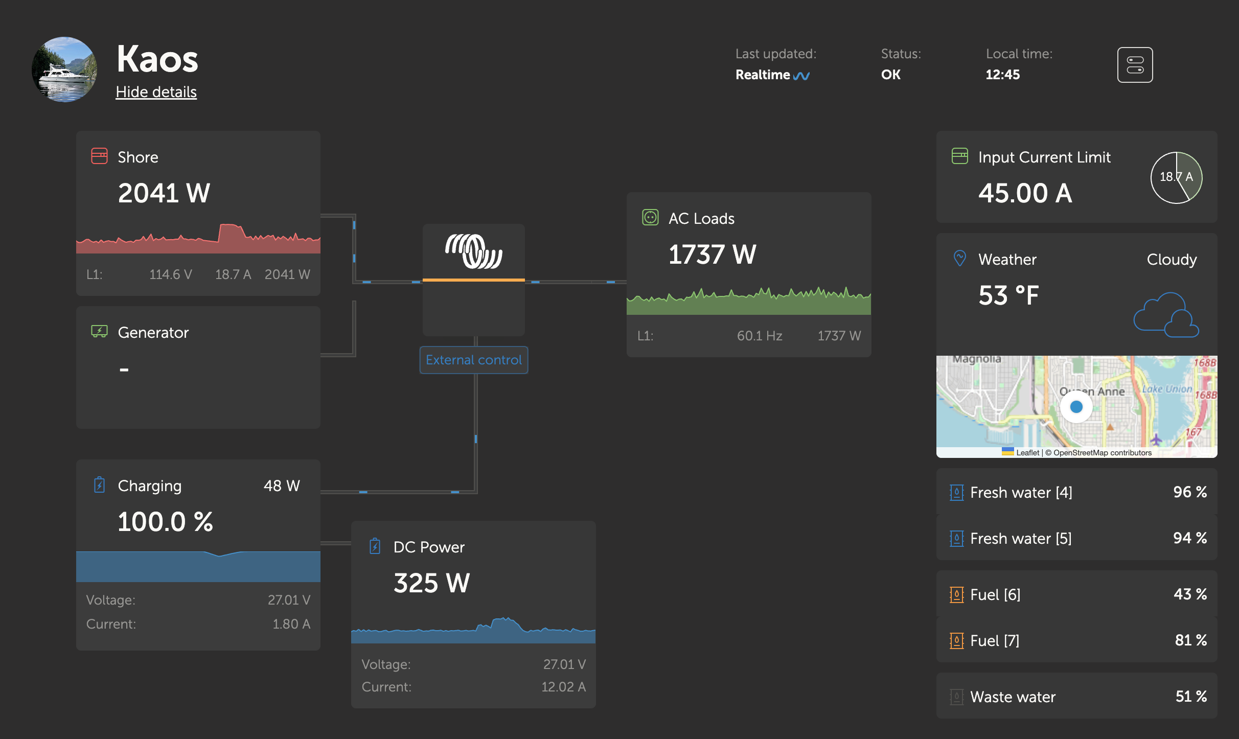
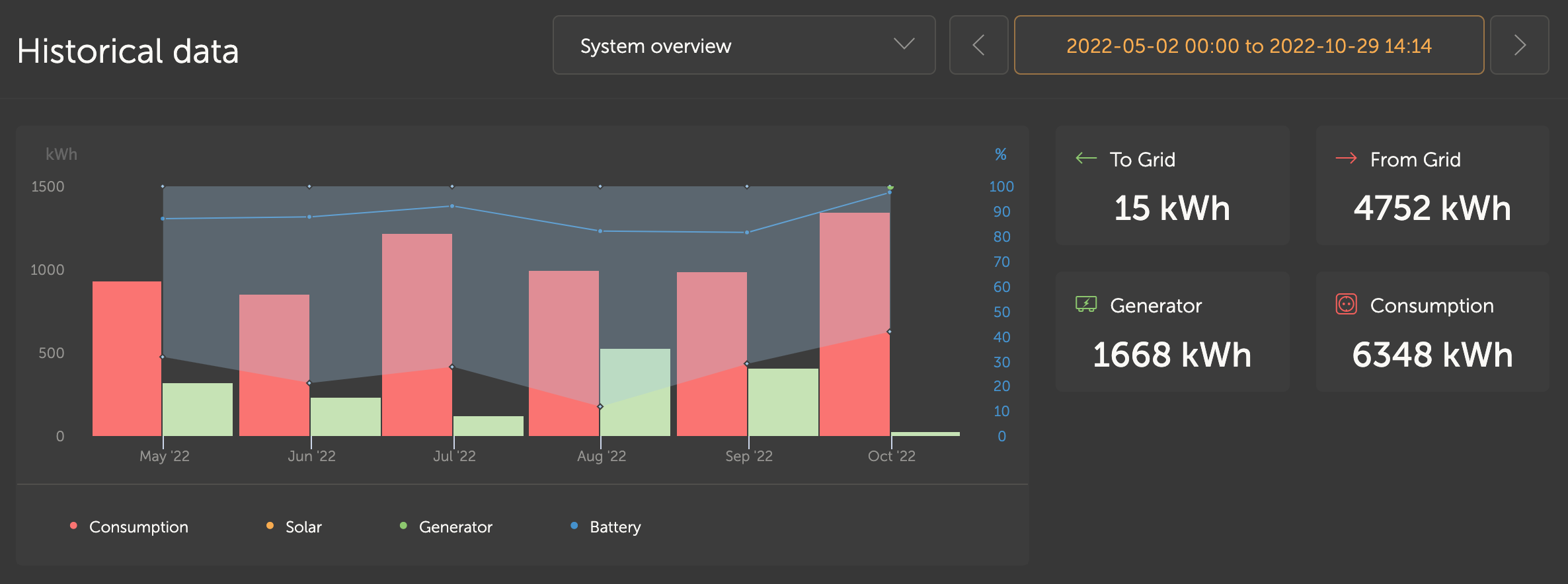
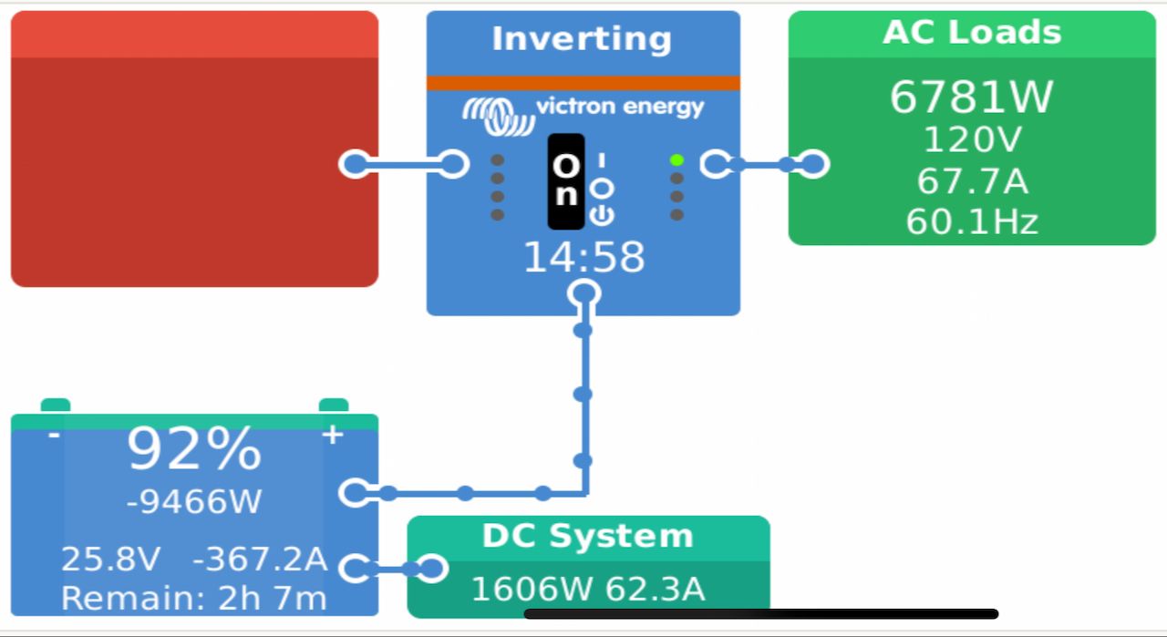
Using the System
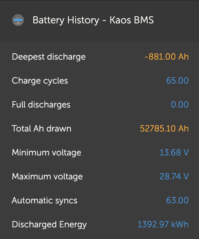
So far I have been extremely pleased with the system. Since installation, it has run flawlessly without any issues for 6 months in all sorts of conditions. During this time, I was at anchor 70 days and ran the generator about 65 of those days. Almost every time I ran the generator, I ended up running many other systems including the water maker and laundry, putting more load on the inverters. Almost always, the generator is at 70-80% load during the entire run time, exactly as I had planned.
The capacity is enough to run the whole boat for 2 days without charging, and probably longer if we weren't so lazy. As with any other boat I've had LiFePO4 on, you tend to not be as crazy with managing lights and electrical usage, which I'm OK with. If a system makes my time on the boat less stressful, that's a win in my book.
Visibility and control has been great. The other battery banks have been charged well, and the changes to cabling, fusing, and connectivity have not caused any issues. I've noticed a more stable power system in general, especially on the 12 volt side since it is being supplied by fixed power supplies at 13 volts.
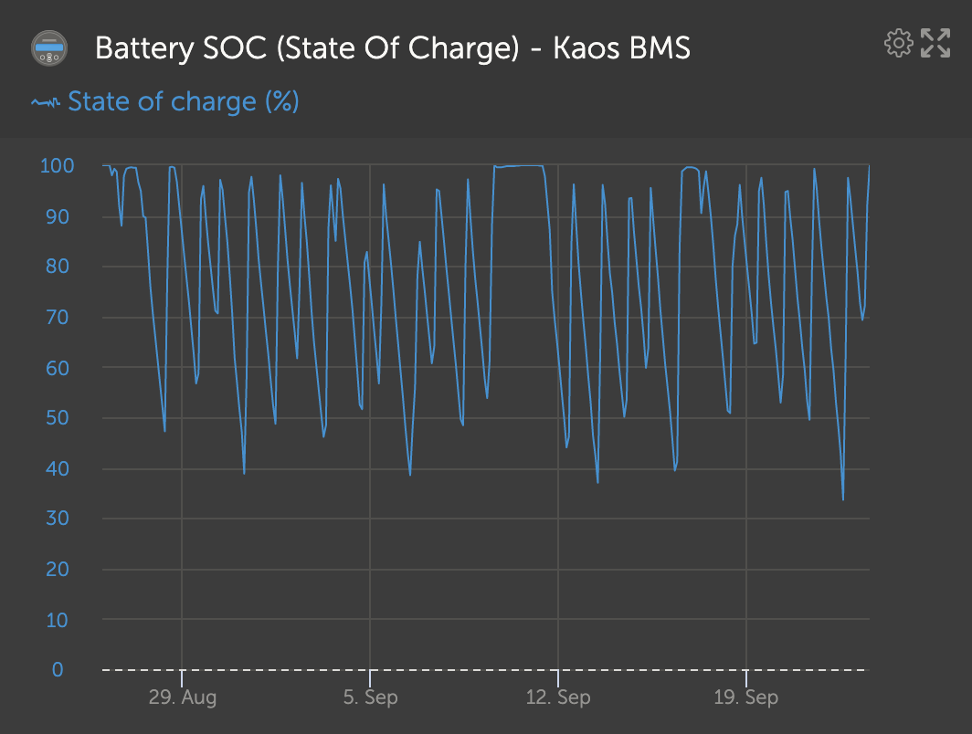
Average generator run time per day is 1-2 hours, depending on state of charge and also how much water I need to make with the watermaker. Since everything is on inverter, it also means we can use the boat systems whenever we want, and choose when to run the generator if it is more appropriate. That takes a lot of stress off of the captain having to plan when to run things, and worrying about making noise late in the evenings. We even ran our air conditioning while at anchor a number of days this year just on battery power with the smoke and hot temperatures. I'm very happy with the reliability, visibility, and capacity of the system.
Challenges
12v windlass - this is connected to the 12 volt house system which gets power from the 3x Victron Orion 70A DC-DC power supplies. During normal use, there aren't any issues, but if the motor is put under higher loads, there is a voltage sag. That results in voltage sensitive things restarting or power cycling, which I want to avoid. Eventually, I will be replacing the windlass motor, or I might upgrade the whole windlass to a slightly larger size, and switch to 24 volts. This will then run back to the existing 24 volt thruster bank and get it off of the 12 volt DC-DC bank, which will eliminate this issue.
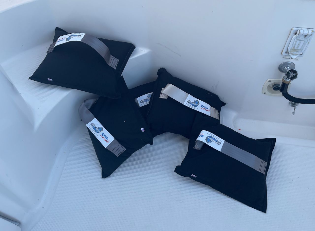
Listing - removing 10x GC2 batteries from the starboard lazarette was great in terms of removing weight, but it created a list. I completely reorganized the storage in the lazarette, but there was still a list. I ended up purchasing a number of 50 pound ballast bags from Wakeballast and placed them in the starboard side to correct the list.
Orion data - there's no way to get any data out of any of the Orion DC-DC power supplies for my 12 volt system, and you can only get data out of the Orion-Tr DC/DC chargers via Bluetooth and a phone app. It would be great if Victron added at least some basic data that you could plumb into the GX platform.
Lynx limits - there are limits around the Lynx distributors (max of 4, and I have 5), Lynx Smart BMS, and Lynx Shunt that are all weird things to work around from the data gathering perspective. None of the issues cause system problems, but for the cost and complexity, you would think they would have thought about these issues. Some are supposed to be addressed with future firmware, so we'll see...
Final Thoughts
The new power system has been amazingly reliable, easy to see all of the data and status, and provides a wonderful amount of capacity that allows us to be quietly at anchor for multiple days. Simplifying the AC panel down to one 120 volt AC input and putting everything on inverter has really made my job as captain a lot easier when it comes to dealing with power, and it means crew and guests have an easier time as well. There are still some refinements to deal with, and some small challenges to overcome, but that's what I love about working on boating systems - iterative design and continuous improvement. After all, this is version 1 of Kaos system - who knows what will be in version 2!
Archived Community Comments
These comments were posted on the SeaBits forum before February 2026. Scroll down to join the current discussion.
Hi Steve! Wow! My Victron LiFePO4 system can’t hold a candle to yours I did have a problem with ours this summer, however, and I’d be interested in your thoughts on working around the issue we encountered.
We have a 12.8v/330ah Lithium battery as our house, which I installed in April of this year. It has worked well since - I REALLY like the advantages of the Li pack vs the AGMs it replaced – with one notable exception: On a sunny day at anchor in Rockland, ME, the BMS board inside our house battery just stopped - it went dark on Bluetooth, and shut off both the charge and load buss switches (BatteryProtect 220a devices). Immediate action drill was to open up VictronConnect and look for the battery (fail), then open the setee containing the battery and feel the temperature (cool). The SmallBMS was showing a red light instead of the usual blue, and both control leads were low, which is why the switches were off. Battery voltage was fine (13.35v).
There is a section in the manual for the battery that identifies a procedure for “restarting” the control board (in the event of an over-discharge), so I opened up the battery and performed it (lifting one lead off the battery and then replacing it). This did nothing.
I then called my Victron dealer, and he asked me to send him an email detailing the problem and what we had done, which I did.
I then “hot-wired” the control lines to turn both the load and charge devices on - which worked fine, and the battery continued to perform well.
There was a firmware issue identified in the 24V batteries that resulted in the same symptom - except that these cases were resolved by new firmware (1.28) and the application of another lead lift.
I think my board just quit - some sort of infant failure so beloved of all of us in the electronics business. Getting a warranty replacement board took 5 weeks, but when I received the new board, it worked perfectly, and has ever since. Victron seems uninterested in diagnosing my board (at least they never asked for it back).
My real concern now is: how do I prepare myself for a future failure of this nature? My biggest concern, of course, is a failure while in some nasty situation (short final to a narrow entrance in the dark!) but I also want to be able to perform the “hot wire” bit without the kludge I used this time (blue tape and all!).
The “Override Switch” will be a guarded toggle switch in a location not subject to flying hands and feet - that will be easy, albeit with a bit of carpentry to make it look professional.
But I concluded the big concern could be met by providing “non-interruptible” power to three things: The primary chartplotter, the N2K Instrument buss and the autopilot. I also plan to provide unswitched power to the battery monitor (BM702), as dropping power to it causes it to forget the SOC, which is annoying.
I’ve acquired some 120amp and 20a Schottky diodes, which I will install in aluminum boxes for installation when I get back aboard.
If there’s a better way, I’m all ears!
Hartley
S/V Atsa
p.s. Its “4/0” as in “four ought”, not 0/4
That’s an interesting failure case. I’ve heard of at least one other person who had a control board in their Victron battery die, but I forget who it was. I do know they had multiple batteries, so it didn’t hurt them that much in terms of running ability - they just lost some capacity until it could be fixed.
Do you only have one battery? I suppose adding another one isn’t an option
Sounds like an override switch is a good idea as long as its safe and you have some way of proving the battery didn’t shut things off intentionally.
I definitely dislike the whole BMV power situation with some of the stand alone BMS’es from Victron. In a state where things get shut off, so does your BMV so you can’t see state of charge, voltage, or anything else. The Lynx Smart BMS actually has dedicated points on it to run a GX or BMV so that it is always powered, except in really rare conditions where everything is completely dead. The BMS can shut off the load side, but keep the GX or BMV still running so you can figure out what happened, which I think is a nice design.
I fixed my late night 0/4 vs 4/0 dumb mistake, thanks. I have stared at the sheathing and labels on those cables for 15+ years and should know better…
Steve,
Great article, as usual. I’m looking at replacing my dead 500ah 12v battery bank (4x6v Trojan TE35 FLA) with a pair of Vitcron 330a/h 12v batteries and lynx bms, cerbo gx & multiplus charger this winter. I was going to use two batteries for both resilience and capacity - I was worried about the risk of the sort of outage mentioned above.
I’d been planning to use a WS500, in part on the basis of your past enthusiasm, and it’s apparently tight integration with the victron kit. My sailing boat only has an aged (but reliable) 43hp engine, with a second 105a prestolite alternatior (currently with an adverc external regulator) as a charging source. I might change the alternator, but there’s not a lot of room so I might see how the current one copes. Smart load management is a must though, with the engine size. One installer I’d talked to has had some poor recent experiences with the ws500 too and was reverting to master volt external regulators. That adds complexity from a management perspective, but if they just work, combined with a smart shunt, it might be a good way to go. Can you share a little more of your issues with the ws500? On paper they look perfect.
Good Morning, Steve! Yes, only one battery - I could probably add another 330ah, but at this point I think I could spend the money better elsewhere
I might point out that if you daisy-chain your Victron batteries BMS cables, one battery doing this trick will disconnect 'em all. They are a series loop, any one device along the loop breaking one of the leads causes your external switching (BatteryProtect, contactor, Lynx, etc.) to open. Victron suggested to me that using a BMS extension cable would fool the SmallBMS into turning everything back on - which confirmed my suspicion.
I debated adding the Cerbo to the uninterruptible buss, but I figure if I can re-energize the system easily, I will do that before doing extensive troubleshooting. When we’re out at sea, the Cerbo is just talking to itself anyway
TomH, I can recommend the “belt saver” feature of the BalMar alternator controllers - the OO of our boat installed a 120amp alternator, but cheaped out and didn’t augment the single V-belt. If I let the alternator go full-bore, I have to replace the belt every month or so >:8O I have it set at 50% now - belts are a biannual replacement JIC.
EDIT to add: One thing I sure wish I could get to the Cerbo is the battery temp and individual cell voltages - I can see them locally using VictronConnect & Bluetooth, but not from afar.
Hartley
S/V Atsa
Great article. I am getting ready to do a major upgrade to outer 51Beneteau Sense 51. I will be trading out the Cristec chargers and adding a Victron Multiplus 3000/12/120 for the house bank and Victron 12v Dc to Dc chargers running off the house bank to charge the eng, Gen and thruster banks. As an ABYC certified electrician, I am trying to remain compliant to all requirements including E-13.
It appears as if the Victron batteries are not compliant. Not UL, SAE or IEC certified and no external warning that I can find. Do you have better information on this?
Also, in your article you indicated issues with the wakespeed 500. I have a single Yanmar common rail diesel with a Valeo 12 v 125 amp alternator. I need to configure for external regulation and then, I was going to use a Wakespeed. Can you share your issues?
Lastly, I have seen a lot of issues with insurance companies getting squirrely bout lithium. I gather this is not your experience. Can you share who you are covered with.
Thanks
Alan
The issue I had with Kaos was a situation where an alternator was destroyed, and nearly caught the boat on fire. It has not been proven whether it was the alternator, regulator, or something else in the mix, but the complexity of the regulator connected to the Lynx Smart BMS along with the extra wiring bothered me at the time. The way it was wired, and indeed, the tight integration with Victron’s Lynx Smart BMS, should have prevented anything like this from happening, but here we are.
The bigger issue is related - Wakespeed is not an easy product to configure, use, and monitor. It requires a decent knowledge of command line, and even then, the syntax is particularly difficult. Even with all of my experience with it on my boat and others, I still have to go back to the manual almost every time. Beyond configuring, it is sort of a black box. There are some features that aren’t clearly documented in a way that a user could understand, and I have found I have had to experiment a bit, or contact their support. That’s the part that ends up being a bigger issue - did you configure it right? Is it working the way it’s supposed to? And many upgrades have changed functionality that worked a different way - not unusual for a software product in its early stages of life.
I think it is a great product for what it provides, especially for smaller engines that might require a more intelligent approach to load management at low RPMs to prevent overloading the engine. It is also amazing with two alternators, two engines, and one battery bank being charged - the synchronization is very well built.
The other piece to consider is that Wakespeed was purchased by Dragonfly Energy, so that is likely to cause some turmoil for a short period of time. Perhaps this will mean it will get better to use over time, though!
That’s an interesting trick. I have mine connected with extension cables because of the length, and they’re in a loop, so there’s some redundancy there.
This has been a common complaint for years, and I don’t know why they don’t expose this at the Cerbo level, especially with the newer BMS’s which have to have this data internally.
Wakespeed has a similar feature, although more dynamic. Both are great ways to reduce the overall output of an alternator - I’ve used the belt saver / belt load features in Balmar stuff for years in customer installs, and on the sailboats. Definitely worth looking into.
That’s definitely something I considered as well, although it is more of an issue with new build boats than for existing ones.
I don’t have any better information on the certifications - I suspect they are working on getting at least one of those given that the standard is now defined and clear. Not sure what you mean by external warning - are you talking about the requirement to have an audible notification when a BMS event is occurring? They do have that now with the combination of their management products…
See my comments above in my response to @TomH
I have seen a lot of people drumming up concern around this, but the two big insurance companies that I’m aware of out here on the west coast have shown no indications around this as far as I am aware, and I’m covered by one of those. I think the target for some of this has been home-built or DIY systems that are hard for any 3rd party to understand and document, and concerns around how they are installed and what safety measures are built in. I’m not saying those installs are worse than a Victron install - both can be just as bad depending on how they’re installed, etc.
Eventually more insurance companies may start requiring more details around these systems, but just like any other system or item found in a survey, they will want mitigation plans or a surveyor to sign off on how something is installed. Now that we actually have a start of a standard in E-13 (it needs more work longer term), folks can start evaluating systems that don’t meet that and help figure out how to get there. Worst case, they may not want to insure the boat, but there are still other companies out there right now to choose from.
I chose a mainstream brand like Victron partially because I knew E-13 was going to be a thing. I wanted a single vendor for all of the equipment so that there weren’t parts of things certified, and no way to get other pieces dealt with. Even without the batteries having everything that E-13 requires, many surveyors or insurance companies are going to be happier that it is all provided by a large supplier. And with the many thousands of Victron installs on boats, I don’t think the insurance industry is going to immediately not insure them .
I’m just glad we finally have some guidance for these types of batteries in the form of ABYC E-13. Now we’ll have to figure out what that means longer term.
Thanks for another great write up. I was interested to read your, and others’, comments regarding the WS500. I have one. Largely bc I felt that it was important to regulate alternator output with current, voltage and temp inputs for charging my LiFePO4 battery. I’m mostly happy with it. I like all the config settings that are available. It has been very good at getting the most power out of my alternator and controlling the charge profile (much better than my Balmar MC614).
The cons for me include, as you said, the inconvenience of configuring, or changing the config.
And lack of easy monitoring (I’ve considered getting a copy of OffGridSoftwareSolutions.com Windows based Pro config tool, though this would not provide a permanent monitoring solution).
And I have not been able to update the firmware using my PC. I’m fairly computer savy. Putty works but I haven’t been able to get the firmware update to work in spite off trying 2 different PCs, logged in as admin with full privileges, different cables, etc. Fortunately my boat is in Anacortes and Rick has been good about helping me get updated.
My WS500 did shut down once while motoring. The error code indicated an over voltage condition, which seemed very odd. Everything checked out ok, maybe a voltage transient? Anyway, reboot and everything seemed ok going forward.
And… this summer my 10+ year old Balmar series 60 alternator stator fried itself. Although I thought the WS500 should have prevented this, I CAN NOT point the finger at the WS500 without doing a much deeper investigation.
The WS500 seems like a good solution that could be great with some more development and testing. Fingers crossed that Dragonfly Energy will invest in further development of the product.
Next for me will be to connect the WS500 to my Cerbo. Hopefully that will provide a modicum of monitoring.
-Mic
Hi Steve, I’m not sure you understood my comment about the Victron BMS wiring from battery to BMS device - it really is a series connection - if any one battery (or cable) fails, the BMS “big switches” in your Lynx will open and darken your 24V load buss. Try it when nothing critical is going on - unscrew any one connection and see what happens. If you have a battery control board fail, you’ll have to ID which battery it is, then reconfigure the BMS cables so its no longer in the loop. It might be easier to just put an extension across the two connections on your Lynx SmartBMS (at least the lights will come back on!).
I just have the SmallBMS, which, as near as I can tell, is just a couple of switches driving the remote control outputs going to my two BatteryProtect devices.
I sure wish we had access to service info on these things, it would make things a LOT easier to puzzle out!
Hartley
That was the main reason I had them on Rendezvous - the addition of monitoring current.
That is definitely something that Wakespeed does well. I do think they also can run right up to the edge of that, and probably was the reason I have had a few issues.
I have it, and have had it since the very beginning. It is one of the only ways I have been able to configure things as often as I used to have to without going crazy, but it was still problematic. Because of the way things are configured, and the fact that the software is made by a 3rd party company, there were plenty of times I ended up having to factory reset things and start anew, which is super annoying. The software is a great attempt at getting a more usable UI.
I’ve had 2 other customers with this issue as well. I think this is one of the fundamental issues with the technology - it’s hard to configure, hard to modify, and can get into a situation where it is unusable and requires someone who knows it very well. Few other regulators have that issue.
I had this happen a number of times on Rendezvous, and after many, many hours of troubleshooting, was never able to track it down. This was v1 Wakespeed hardware. It happened less with v2.
I really hope Dragonfly help with the supportability and testing too. I think one of the reasons they were interested in Wakespeed is to complement their batteries and other LiFePO4 systems, so they’ll need to make it easier to use if it is paired with drop-in batteries. I have already seen new videos and guides on the website which makes me hope it will eventually change!
Ah yes, I misunderstood what you were talking about. Mine won’t shut off right away, as there is a delay built into the Lynx Smart BMS and other logic you can tweak to give you a “pre alarm” before everything goes dark. Still, at the point where that timer runs out, you’re done… This was one of the reasons I considered a 12 volt AGM battery sitting on the same bus as the DC-DC power supplies and 12v distribution bus. At least if I lost the 24v side, AC power would die, charging would go down, but 12v would still be up and running, which means basic instruments and navigation, lighting, etc. The design allows for this to be added in with about 5 minutes work, and I have a battery sitting there that could be used. Might add it in for v1.1 of the design…
I have access to some of the service info and training materials. Some of it is in there, other parts are alluded to or you figure out during the training, and even more are just undocumented. Lots of folks have complained over the years about this. Other vendors don’t have as much of a problem, but they also have far less features too, so…
Thinking about the parallel vs split phase inverters, is there any reason you couldn’t have run them in split phase and just connected both to the 120v generator output? Would the inverters have complained about both inputs being in-phase on generator power?
I tried that and it did exactly as you mentioned. It detected the same phase and refused to engage or use the generator power.
Darn. Would it make sense to add another panel for loads (like the block heaters and chargers for the starting and thruster batteries) that you’d never want to run on inverter power and just put a manual (or even automatic) shore/gen transfer switch on that panel? It would allow you to at least get some use out of the second shore power leg.
I could, but it would really only be a few things like the block heaters. I can’t even think of anything else that I wouldn’t at least want the ability to run off of the inverters.
The chargers for the start / thruster banks don’t rely on the inverters - they come directly off of the 24v bank, and I always want those on just in case something happens with one of those banks so that they’re always charged.
Adding another panel would be relatively easy, other than the fact that I would not have visibility to it with the current system, and would have to monitor it another way or add it in somehow to the existing one. But that’s easily solvable.
I guess the challenge in general is what would I want on that panel? Just the block heaters so far…everything else I would like to run off of the inverters.
I haven’t run out of power at any point. The one 50 amp leg has been more than enough for everything. Having Power Assist helps whenever I go over that, but that doesn’t happen often. I’m also working to replace some things that are less efficient - earlier in the year I removed a really old air conditioning unit in the pilot house which used a ton of amps on startup, and replaced it with a bigger unit with slow start and lower amperage usage. Same with all of the lighting, microwave, stove, and more.
Re: Wakespeed, I’m installing one now and I do think the support has suffered under Dragonfly. So far they have never responded to emails sent to support@wakespeed.com and I am able to get phone support, but the sales / tech agent I’ve spoken with didn’t seem very well informed about Wakespeed (not surprising given their main business is selling BattleBorn).
He gave me incorrect information and when I pushed back on that, asking if he could check with the tech team, he said he knows all there is to know about the product and they’re not likely to test a new configuration. (I asked if you could extend the CerboGX crossover Cat5e cable with a RJ45 coupler and he said you cannot and shouldn’t do that, he thought - but the package Wakespeed shipped this cable in has a print-out saying you can do that).
Also a good deal of conflicting information and/or typos in the manual. Oh well, it likely is still the best option for a lithium system. If I could get support from someone actually at Wakespeed that would be great though.
That’s not great to hear, but I sort of suspected this would happen.
I think I posted about it before, but I exchanged many hundreds of emails with the original founders of Wakespeed, mostly to deal with continual issues with firmware upgrades and to tune my dual alternator setup. It was extremely painful because of the poor documentation, and the very esoteric choices made with the configuration syntax and approach.
I had hoped that Dragonfly would unify or at least push some of that to be more user-friendly, but I think we’re still in the transition period since they were purchased. I do think that the only way Wakespeed’s product could be successful under that brand would be for it to be more plug-and-play with pre-built configurations that could be more easily pushed to the device.
I removed my Wakespeed earlier this year due to issues with the connectivity to the Victron Lynx BMS. I used a coupler for my setup and it worked fine, at least that part did. I am considering re-installing the Wakespeed now that their initial versions have been out for a while and hopefully the initial bugs have been worked out.
I’m a little scared about getting to the configuration part but I think they’re trying to make that more layperson friendly. It appears maybe they rewrote the manual because the printed quickstart sheet they shipped me says to see the “User Guide” for details about voltage sensing. But there is no “User Guide” - the downloadable pdf is “Product Manual”, and doesn’t contain a section on voltage sensing. I’m guessing that was in the old user guide.
The manual actually only passingly mentions the CAN programming mode (and separate communications manual), focusing on using pre-selected profiles through the DIP switches (those only have one profile for LiFePo4 though, with oddly low voltage - 13.8 absorb - probably erring on the very conservative side).
But there’s also an Android/iOS app now which allows you to generate a .txt config file from some preloaded LiFePo4 profiles (BattleBorn, Victron, but no Kilovault). And I just discovered if you enable “expert mode” you can edit the charge parameters (helpful if they don’t have your battery profile). It’s basically a GUI for the txt file.
These seem like revision 2 or 3 of the various instructions and manuals that I have used before to set the Wakespeed stuff up.
You can use a USB cable to the port inside the unit and a terminal program (putty on Windows, iTerm/terminal on Mac) to configure things using the command line, a 3rd party piece of software sold by Off Grid Solutions (or something like that) which does most of it, or the Android app to generate a configuration file.
The USB cable approach requires you understand the complicated syntax and build out your configuration either by hand, or based on a template. It’s very time consuming and prone to error.
The software option is probably the one I used the most, but it’s not always in sync with firmware changes and syntax issues. I’ve ended up with mangled configurations a lot of times. It’s also a very basic piece of software with difficult UX. On top of that, you have to pay for it and it’s not offered nor supported by Wakespeed.
The Android app asks a bunch of questions and spits out a configuration you can then download to the device using a messy USB cable option, or generate a file and push it to the device using Windows and a bunch of batch files and a USB cable. The iOS version when I tested it did only about 50% of the Android one.
The user guide and card is also confusing. You have to set the dip switches for the size of your bank, type of batteries, and other things, but you also really, really should upload a specific configuration based on your battery charge details if you’re using LiFePO4. They used to keep examples of various battery manufacturer profiles on their website - I don’t know if those are around anymore, but I probably have some old copies. You use the Windows batch files and USB cable to upload these.
Any way you slice it, it’s difficult to configure with poor documentation and confusing syntax and approach.
The trick for me was removing the USB device that windows automatically installed and manually putting in drivers that wakespeed provided. Now I can update the firmware again (including through the offgrid software).
Great hardware that fills a void. But hampered by its difficultly to set up custom configs. Custom configs is why I bought the WS500. And the documentation… well, I second everything said above. If Dragonfly would hire an experienced tech writer that would be a start.
And yes, I also learned the hard way that you need to use the Windows drivers that are compatible with the WS500.
I just got my boat back in the water and I’m planning on implementing the WS500 to Cerbo GX comm link this spring. So at last, I’m hoping that I can have some visibility into what the WS500 is doing.
Ah good note on fixing those drivers. I’ve not had this happen, which is surprising since I’ve worked on my own many, many times, and others as well. Must be super lucky!
I tried the beta version of this and had bad results, but I am looking forward to trying the WS500 again here in a month with that link for the same reason.
I actually have an update planned in the next few weeks on how the system is doing. So far, so good - very happy with it - more details in the article!
Update - I did implement the WS500 to Cerbo GX (CAN Bus) comm link and have been using it this summer. The short version is that this feature has added a much needed level of visibility into the status of the WS500, including English error messages. Highly recommended.
I also have my Cerbo GX connected to my Raymarine Axiom Pro MFD via Ethernet (RayNet) which allows the Victron app on the MFD to replicate display & control of the Cerbo GX on the MFD at the helm. So the WS500 device data is visible at the helm. Nice!
I also have my Cerbo GX connected to the NMEA2000 bus. So the Cerbo GX broadcasts data from the SmartShunt onto the NMEA2000 bus where it can be displayed by the MFD and other instruments on the bus.
One of the very surprising benefits of having the WS500 connected to the Cerbo GX, to the NMEA2000 bus has to do with the engine RPM. I have the typical Yanmar/VDO tachometer at the helm but it’s old and “sticky” and not very accurate. I was poking around in various displays on my MFD and discovered that the screen that displays engine data is now showing very accurate engine RPM (based on my programming pulley ratios in the WS500). Knock me over. I didn’t have to do anything. Unfortunately, all the data that the WS500 outputs on the CAN Bus is not well documented (I wouldn’t consider Config Guide-Appendix C sufficient). So some experimenting is on the list of things to do to see what other useful WS500 data can be displayed by NMEA2000 connected instruments.
Regarding the custom CAN Bus cable needed for connecting the WS500 to the Cerbo GX: You can purchase a pre-made cable or make you own using the wiring diagram in the WS500/Cerbo documentation. I chose the latter because I don’t like loops of cable stuffed into wiring runs. As for cable length and using extenders, the CAN Bus spec says that maximum cable lengths must be between 500 meters(125 kbps) and 40 meters(1 Mbps). 40 meters probably covers most of our boats.
Good to know! I may do this myself.
This is a nice feature and I’ve used it before myself and for clients. Did you know you can also see this on a phone or a web browser on a computer by going to your Cerbo IP address and adding /app/ at the end? You’ll get the version that shows up on a chart plotter instead of the usual one!
Ah yes I recommend this with any install.
Nice side benefit!
Yup I did this on Rendezvous which allowed for some limited data at the time. They’ve increased that as well.
Glad you have more visibility and info with your system!