With my LiFePO4 power design complete, I was excited to install and use the new system for most of this sailing season. The installation took longer than a traditional battery installation, and had more complexity, but turned out to be a fantastic setup for the longer trips I went on this summer.
The installation took multiple weeks, with phases of the project chunked up to have the smallest impact to power on the boat. This allowed me to continue working on board, and planning out the pieces of the install without sitting in the cold and dark in early spring/late winter.
I ended up removing all but one battery from my existing system, but left everything else while I began the install.
Proper Crimping Tools
Proper tools were essential, as usual, to a project of this scope. I chose to crimp and terminate all of my own wires so that I could get exact length runs and save myself having to document and measure everything perfectly for someone else to do it online as I had in the past. In addition, it gave me more flexibility as I could move stuff around during install to find the exact right spot.

This is one of the worst crimping tools you could ever use – a very poorly made General Hydraulics. Not only are the dies that insert into the jaws completely mis-labeled in some cases, but they are either too small or too big in general. Stay away from this one!
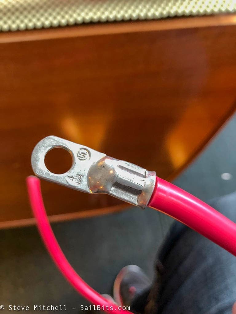
Here’s how the crimp comes out with that tool. Not terrible, but surely not as good as it could be. On bigger wires, it absolutely mangles them.
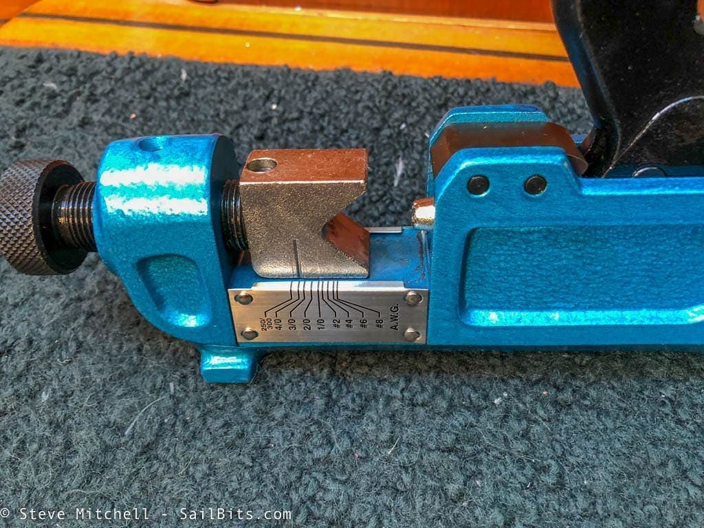
Another one to steer clear of is the Ancor large lug wire crimper. I had one of these that I got essentially for free but had never used. It looks impressive, and has the Ancor name, which might mean it is OK.
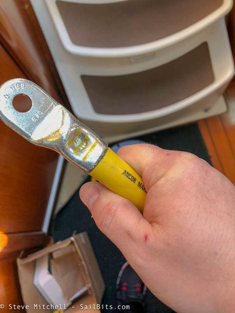
Nope this one sucks too. While this won’t come off unless I really try, the way it crimps is essentially by smashing a cross like blunt instrument into one side. I did not like the quality of the crimps.
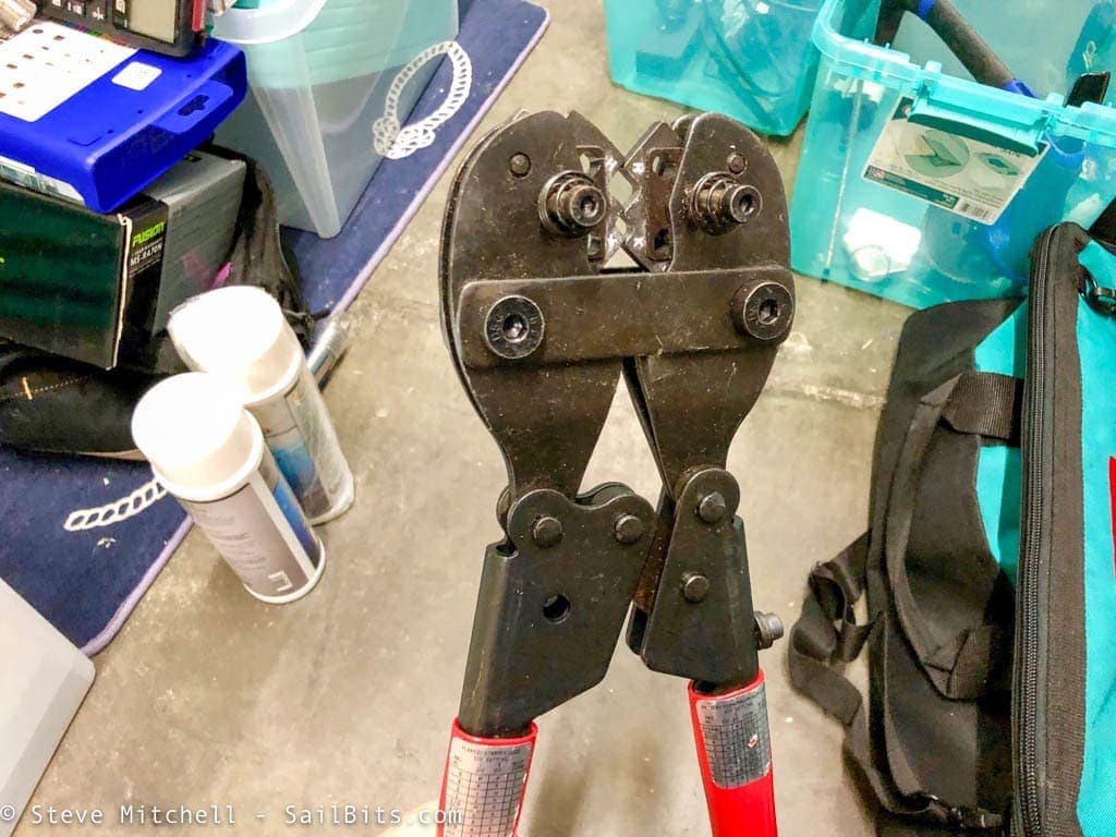
I had been using the FTZ 94284 crimp tool on projects for the last year, and had been very pleased with the quality of the crimp. I found this on MarineHowTo.com at Making Your Own Battery Cables which I think I’ve linked to before. I highly recommend reading the entire article to see how bad other crimpers are.
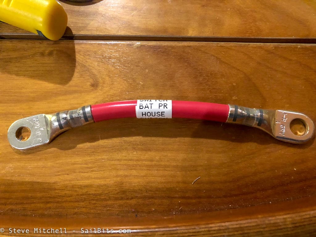
A nicely crimped short cable!
The Wiring
Given the location of the battery, inverter, distribution and other pieces, I knew I was going to have to run some fairly big wires. In fact, between the battery and distribution, I used 4/0 AWG – the biggest I have worked with in a long while. It was like trying to tame a big, angry snake.
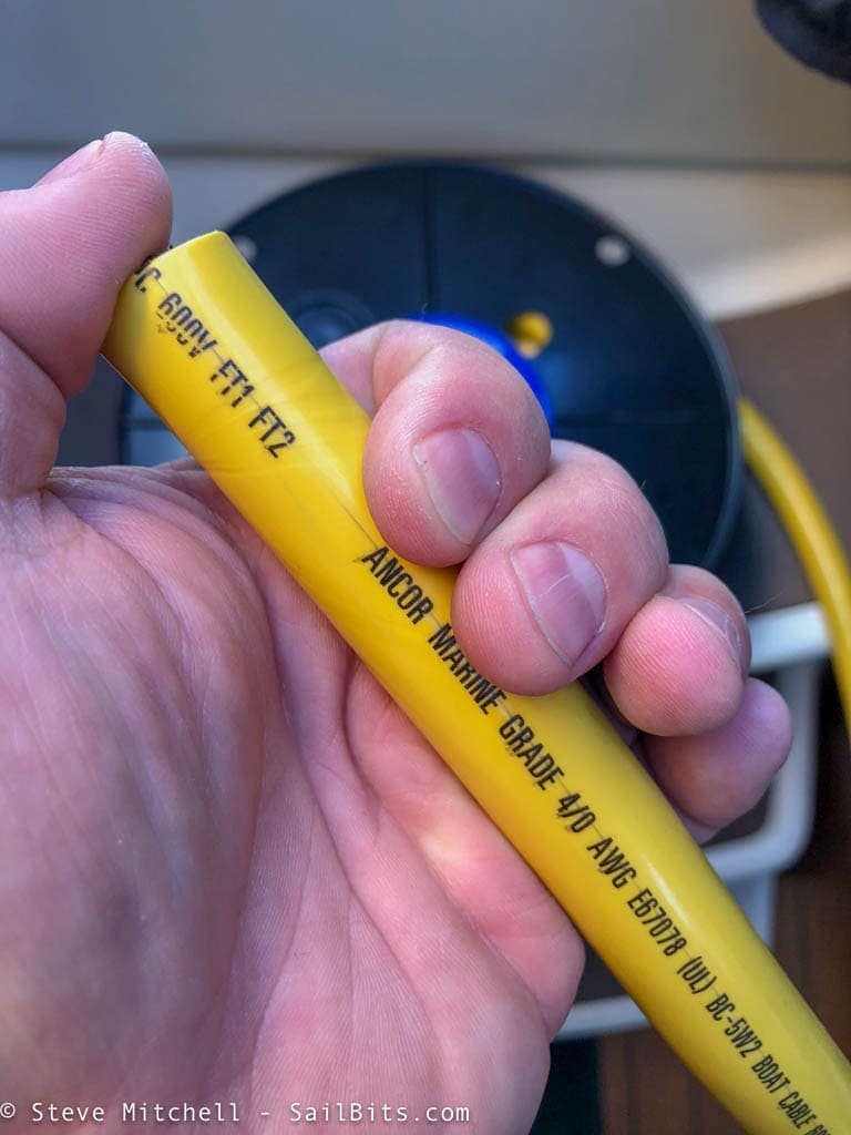
Along with proper crimping tools, you need to make sure you have very sharp and powerful cutting tools to ensure a nice clean cut, especially with wire this size.
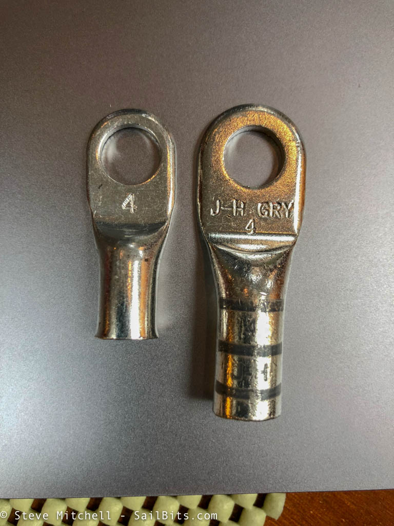
For most of my connections, I used “power lugs” which are the ones on the right in the photo above. They have a longer metal barrel that makes more contact with the wire, and usually call for 2 crimps which means better overall connection. The lug on the left is considered a “battery lug” and I used them on smaller connections or when connecting to the battery, as the plates where the hole is are better sized for that application.

I had a lot of different sized wires, and ordered all of my lugs from my local favorite store Fisheries Supply. I liked the FTZ branded lugs – they were clearly marked with colors and labels, matched my crimping tool chart, and came in a 10 pack bag for a lot less than Ancor and others.
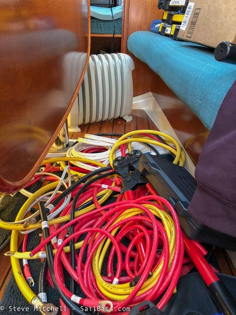
There were a lot of wires I removed, but I tried to recycle as much of the good wire as possible. It was still a rats nest at times while I swapped things around.
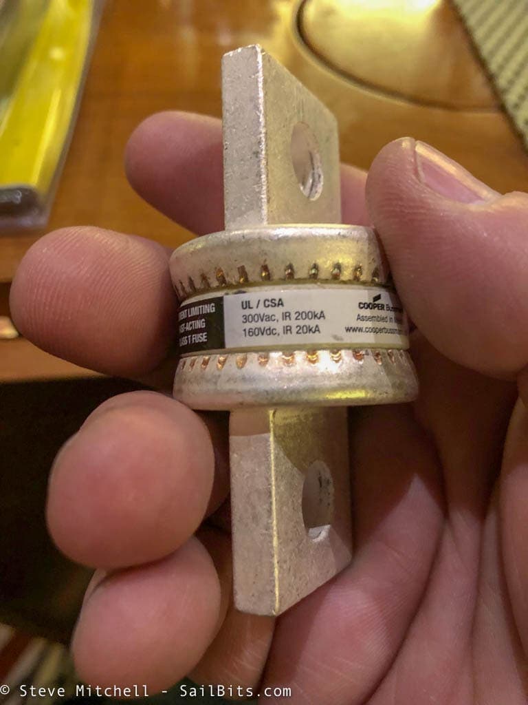
The other important piece with any DC electrical system on the boat is fusing. For the inverter and battery I used class T fuses appropriate to the max current, plus there were fuses that I updated or added for all of the other major pieces – DC house loads, heater, solar, etc.
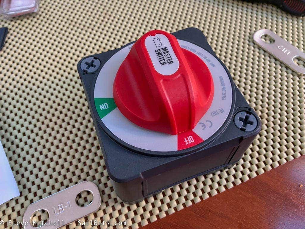
I added new battery switches both at the inverter and the battery itself. The old setup did not have a battery switch near the inverter, and the switch for the house batteries was further away than I’d like.
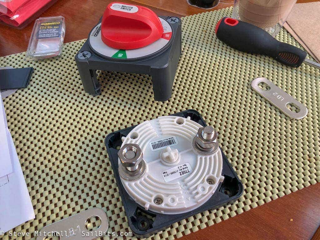
I used Marinco Pro Installer Series switches which have a couple of nice features. First, the entire front of the unit comes off so you can wire things much easier than trying to get to the back side of the switch.
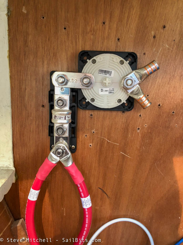
In addition, you can get various bars and connectors along with busses, fuse blocks and more. To connect them you use appropriately sized bars to link them together. This prevents having to use a jumper wire and the extra space required for the wire in between the two devices. I really like these, and will be using them in the future.
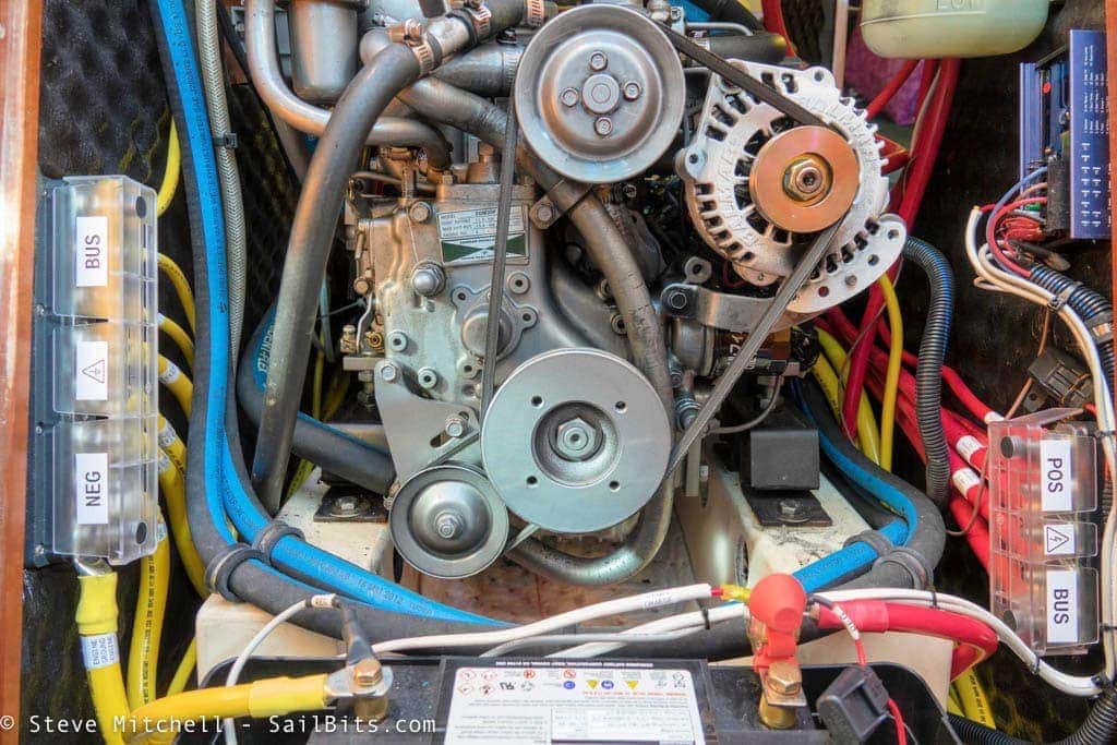
I also moved the main positive and negative busses to either side of the engine space. They were originally near the back of the engine, which is OK access, but this spot is better suited to reach the inverter, batteries, and everything else. The heat that is generated by the engine was a concern, but I sized the cables up considerably for everything, and there really is no other area for these to live. I’m happy with the location and updates that make it easier to see and use.
The Battery
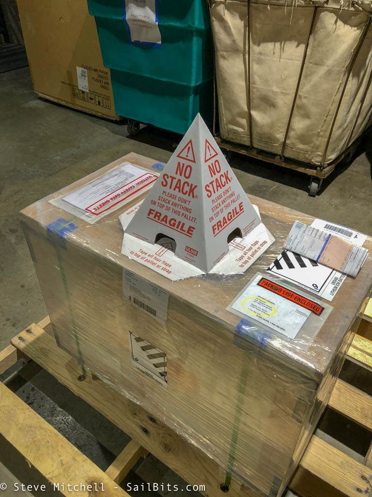
The most expensive part of the system, and the most impressive in my opinion, is the 300 amp hour Victron LiFePO4 battery. It arrived via special freight company in a very special box, topped by a special device preventing anyone from stacking something on top of it, and monitoring drops and shakes.
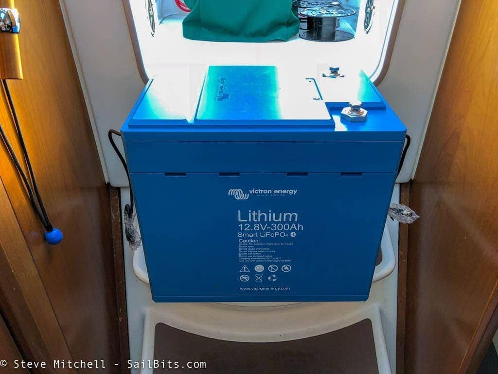
It took some careful planning to get it aboard, as the battery itself is 112 pounds and quite bulky. There are some nice handles on the sides, but it would be nicer to have some hard points to lash to. This single battery is replacing almost double the weight in carbon foam AGM (Firefly) batteries, at about the same size as a single battery, or only 1/3rd the space. Quite impressive!
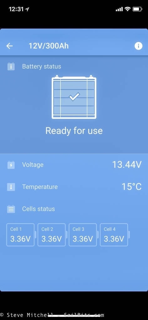
The battery has a Bluetooth radio in it, and I was able to query it before I even had it all connected up to check on the cells and overall health. In fact, before I even unpacked it from the shipping crate, I could do this – pretty neat!
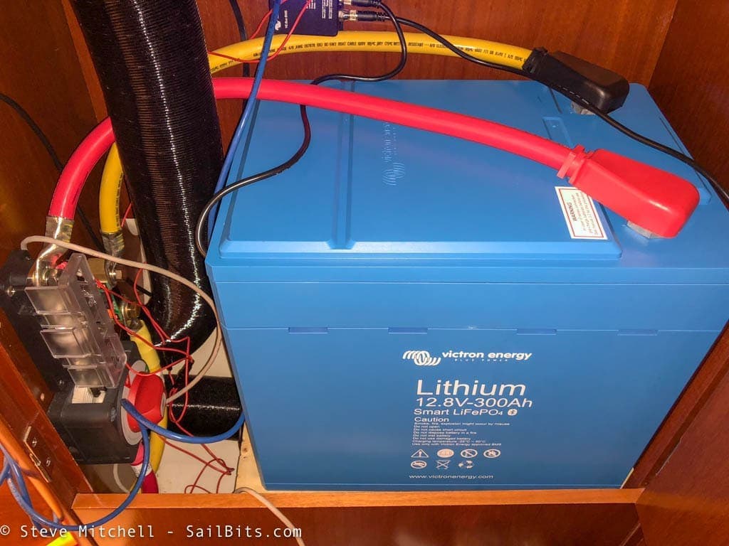
The biggest challenge with installation was finding a place for the 300 amp hour battery, but I eventually chose the bottom of the master stateroom storage closet. I built a very strong shelf in the base, moved some heating ducts around, and mounted the battery switch and fuse for the positive side, as well as the Victron BMV-712 shunt for the negative side. This picture is mid-installation where I was validating cabling lengths and such – the final solution has since been cleaned up considerably.
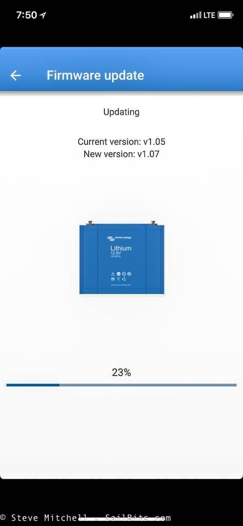
One thing that was fun and also terrifying is firmware updates for the battery. These are delivered over Bluetooth as well. I guess everything has software nowadays!
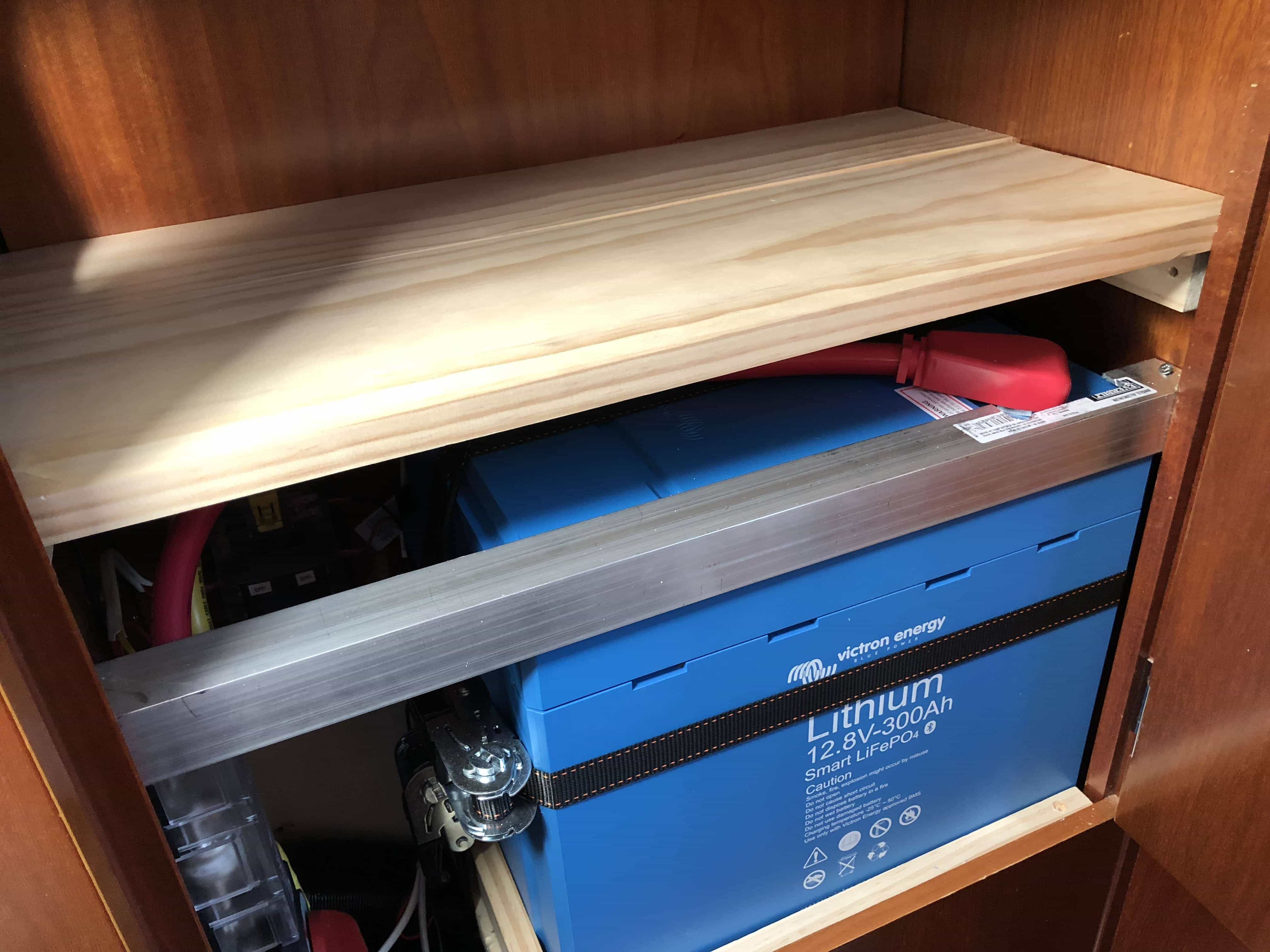
The final install for the battery included three straps holding it down to the new shelf, multiple blocks around the battery screwed down into the shelf, and a big piece of aluminum angle keeping it secure as well. I cut a large portion out of the end around the positive terminal, and covered it in plastic to prevent any issues.
Not only was this far more secure than the original batteries, but the weight was on the port side, eliminating the massive list I had with the previous setup! That was a major goal for this project, and early on during installation, you could feel the list disappear.
Inverter
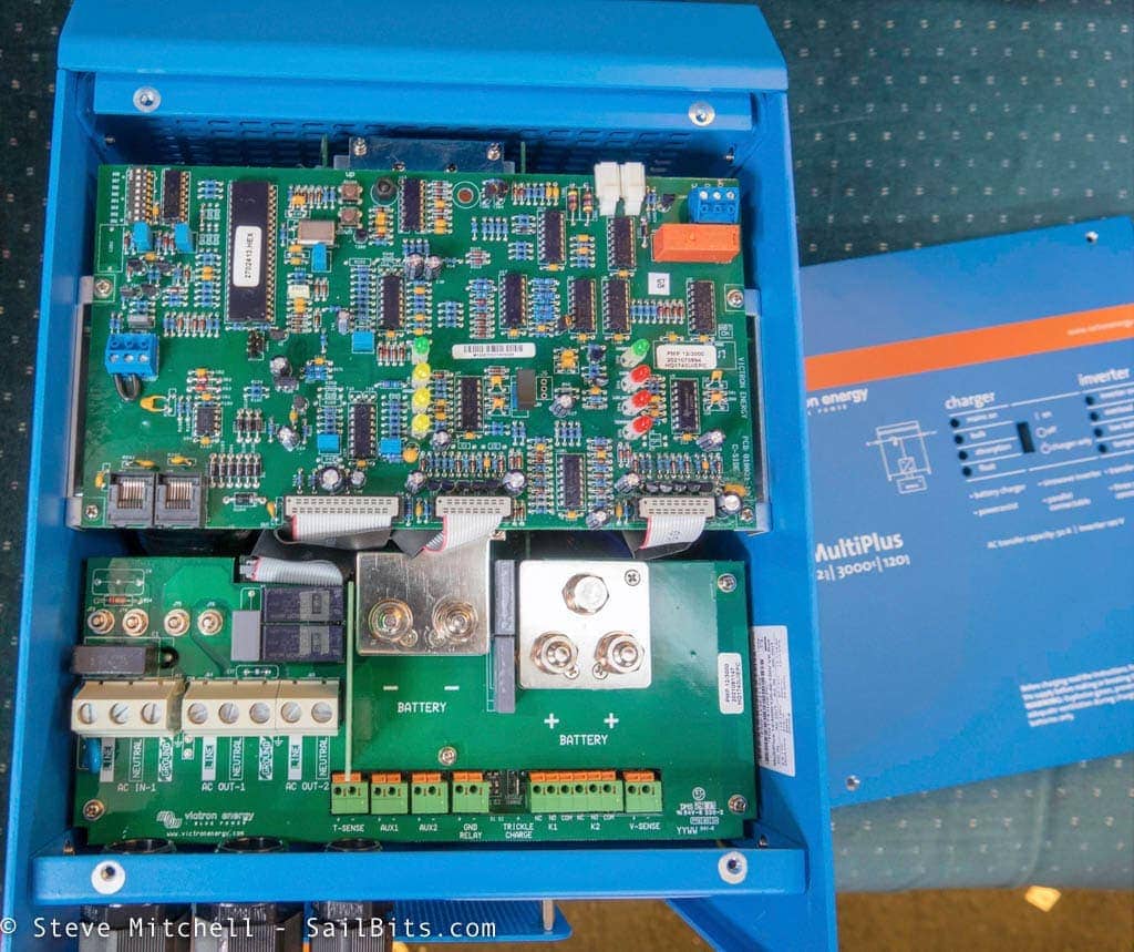
The Victron MultiPlus 3000W inverter is a thing of beauty. Not only do I get 3000W of inverted power, but also 120 amps of charging power, dual AC outputs, and a secondary circuit to charge my start battery. Everything was clearly labeled and had plenty of space to work on, which is a nice change as well.
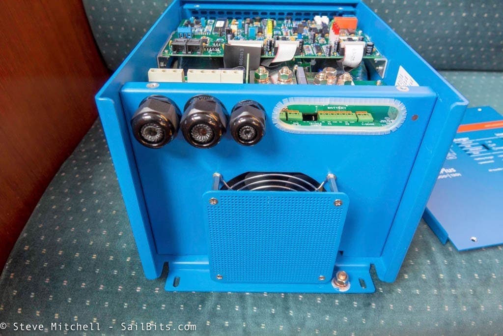
The MultiPlus felt better constructed than the MasterVolt and other equipment I have worked on before. I also like how they added a nice aluminum guard under the fan to prevent any damage.
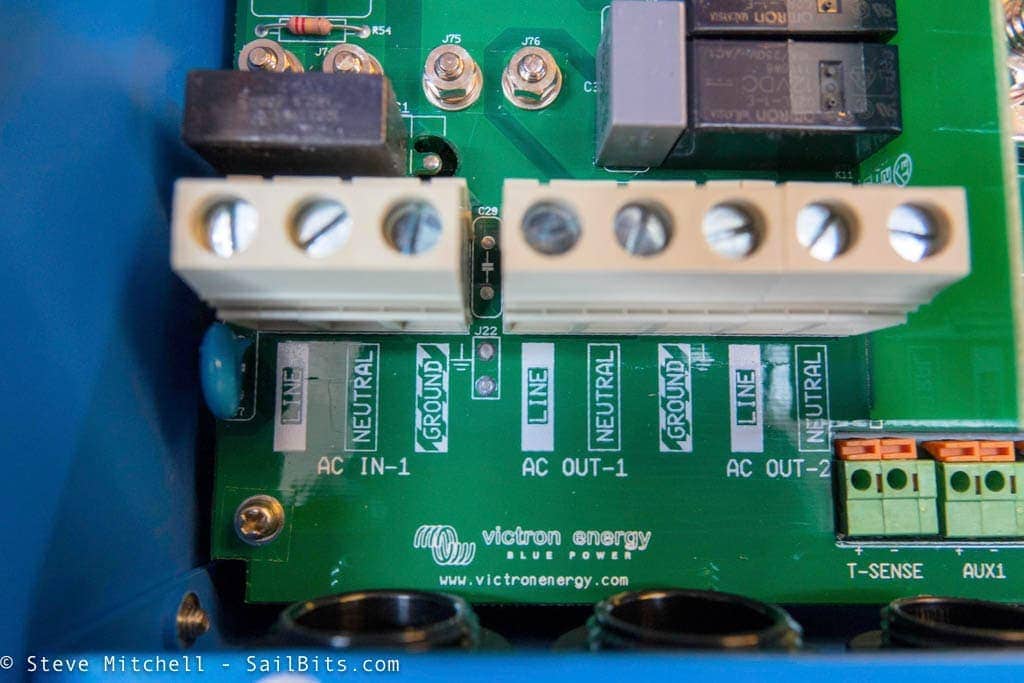
One of the main features I planned on using is having the main AC input from shore power go directly into the inverter, and then utilizing the dual AC outs for inverted and non-inverted power. This would allow me to control all AC power from a central point, monitor it in one place, and use some of the neat Victron features in case of a smaller shore power source.
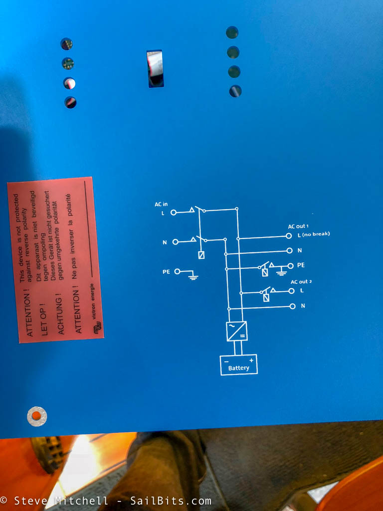
I like how Victron includes an electrical diagram of the inverter details on the inside of the front cover. Useful instead of having to dig around for a manual in case of an issue.
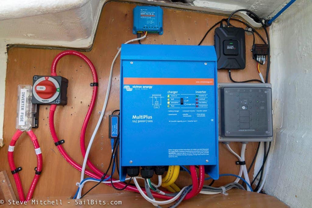
I ended up having to install the inverter/charger in the same space as the old one, which was a bit further from the battery than I wanted, but it was really the only location available. I did add a new ELCI breaker (on the right) as well as a battery switch and inverter fuse properly sized for the 3000W load. This was just before I cleaned up all the cables and made it look nice and tidy.
You’ll also notice I have two 2/0 AWG cables for positive and negative on the DC side – this is due to the amount of amps the inverter could draw from the battery. Victron actually recommends using 2x each of these cables when you are at a certain length and overall amperage, essentially creating a “bigger” single cable out of two. I could have used 4/0 AWG wire, but it would not have given me as much capacity as 2x 2/0 AWG, and was their recommended setup.
Relays and Controls
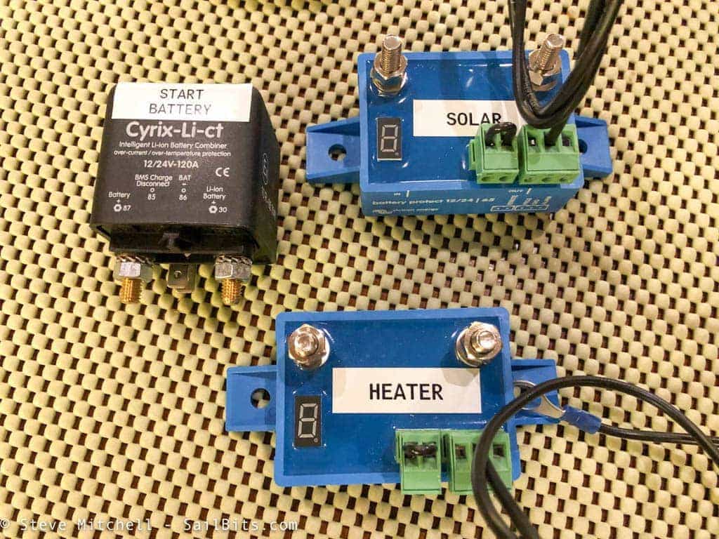
One of the more complicated things with a LiFePO4 system are the controls you have to put in place to protect the battery bank from being over charged, and from being discharged too much. For my setup, I needed two to prevent over charging – one for the alternator, which is the Cyrix-Li-ct, and one for my solar panels. I also needed two to prevent discharging too much – one for my house DC loads and one for the Wallas heater, which was wired separately and ran in fan mode even with main DC loads off.
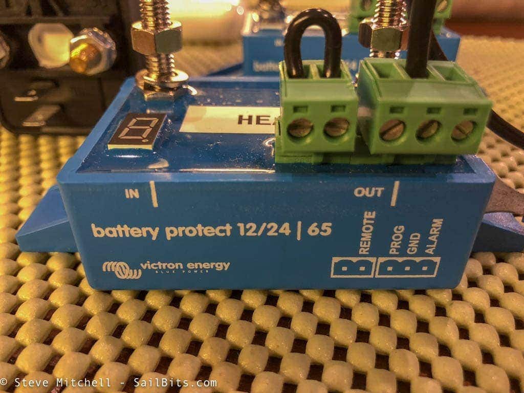
Victron has a number of choices for these relays, the Battery Protect series being the most popular. For a LiFePO4 system with the Victron BMS, you only need two wires connected to the control blocks – a negative common ground, and to the remote pin. This allows the BMS to send the appropriate signal when charging or discharging needs to stop due to either situation.
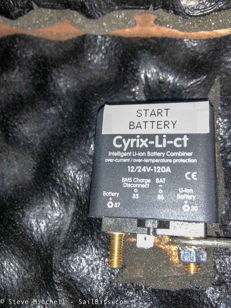
The Cyrix relay was recommended for the alternator based on the hard coded logic inside, but it also was connected via the same methods as the Battery Protect to allow for the BMS to shut it off. The only benefit with the Cyrix is that it didn’t combine the alternator/start battery with the house battery unless certain voltages were seen on both posts. The Battery Protect models did not do this, and happily would remain open/closed depending on the signal from the BMS, which I did not want for the alternator/start battery.
I ended up replacing this later on with a larger version with an indicator light, as I did not like the size of the posts, and never could tell whether it was working appropriately.
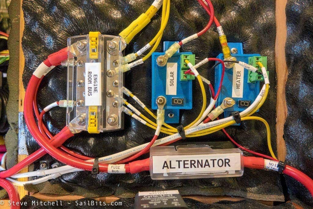
This is where two of the Battery Protects ended up being mounted, further aft of the engine room. The heater gets its power from this bus, and has a Battery Protect inline to shut it off if the main house bank gets too depleted. The Victron MPPT solar controller wiring also terminates here, and another Battery Protect will disconnect it if the house bank is nearing over charge state. Some people have chosen to rely on the Victron MPPT solar controller being connected to the Color Control GX via a Victron control bus, but it was highly recommended to have this Battery Protect, as there are some situations where the CCGX will not command it off.
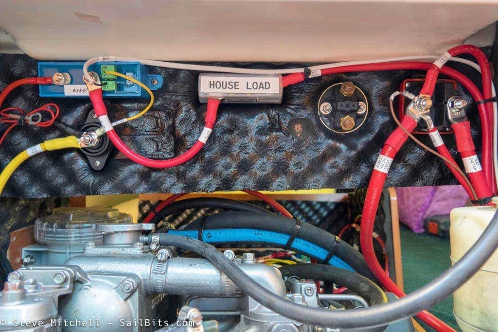
The main DC panel also has a larger 100 amp Battery Protect (upper left) between it and the house battery bank. This allows the Victron BMS to disconnect all DC loads in the event of deep discharge.
The only things that are not behind a Battery Protect are the BMV-712 shunt/meter, and the Victron BMS itself. These are connected to a fused mini-panel near the main house battery, and this is the recommended configuration from Victron. You always want the Victron BMS to be connected and alive, no matter what happens. Additionally, for LiFePO4 batteries, you absolutely must have accurate state of charge and usage, hence the BMV being wired similarly.
Displays and Meters
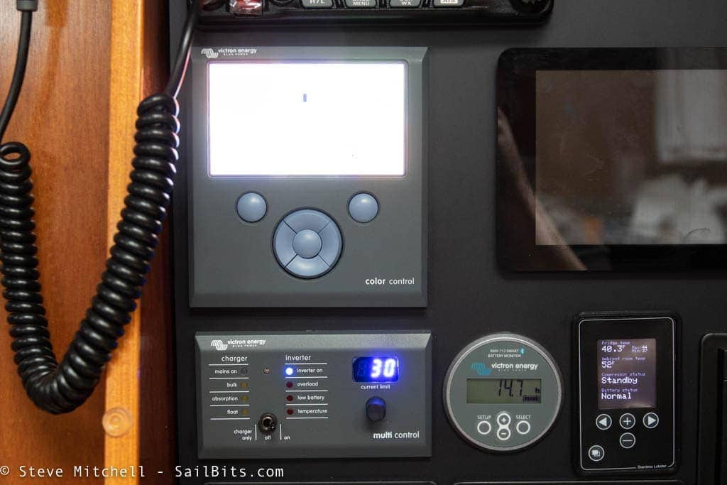
There were three components to controlling the system and seeing what was going on. The Color Control GX is the biggest and most complex, and is in the upper left here – not sure what happened to my photo. Below that is the Digital Multi Control, which is wired to the Victron BMS and allows remote control of the MultiPlus inverter. Finally, to the right of that is the circular BMV-712 battery monitor.
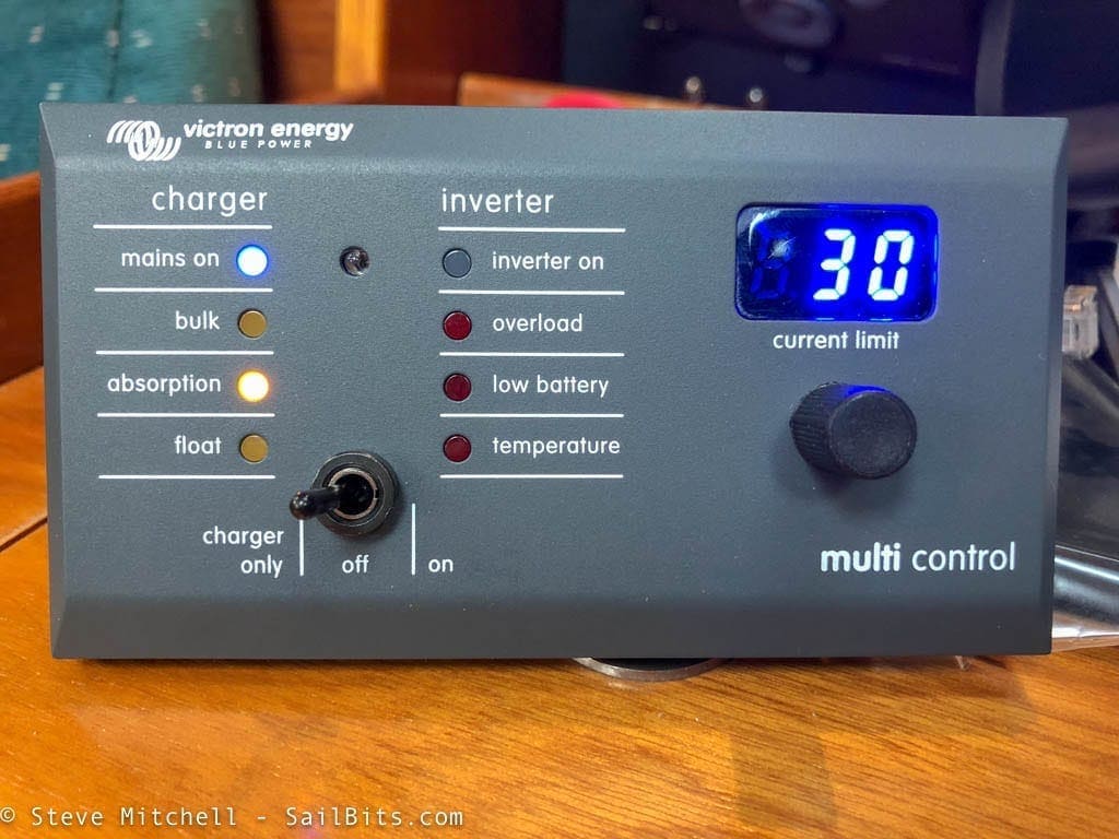
The Digital Multi Control is essentially a carbon copy of the front of the MultiPlus inverter/charger. Victron specifically called out that you needed this component if you wanted to be able to adjust the current limit for your AC shore power connection, as the Color Control GX will not be able to adjust this parameter if you have a Victron BMS. Some users have commented on my other article about designing this system, indicating they did not need this, but they did not have the LiFePO4 Victron BMS, which definitely does require this.
If you look at the Victron BMS wiring diagram, this device is connected directly to the BMS via a Victron (ethernet) cable. I didn’t mind having the panel as it provided an instant way of figuring out what the inverter was doing, and a quick switch to turn things on/off/inverted, which was nice. The real benefit was being able to dial in the AC shore power max current. I visited many marinas that required this due to smaller circuits, or the tendency to trip the breaker at a lower overall amperage.
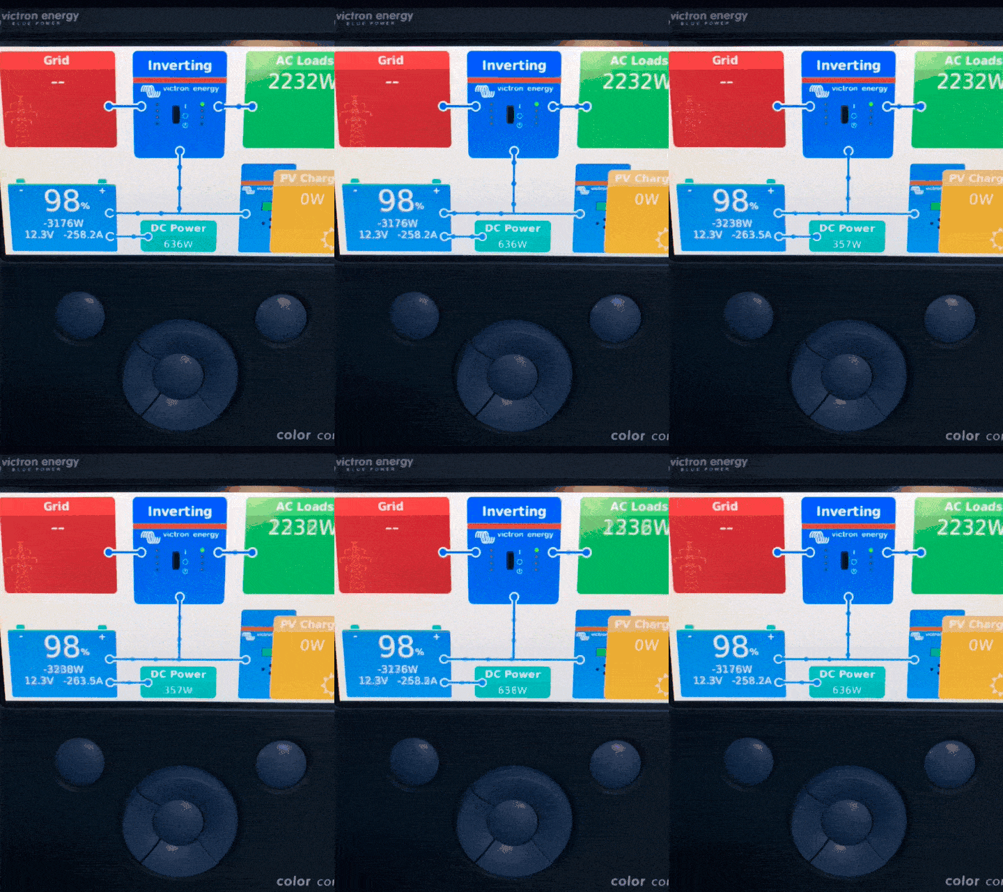
The Color Control GX is a piece of art – not only can you see just about anything about your power system in one place, but you can configure tons of settings, setup alarms, and connect the whole thing to Victron’s portal to see it on your smart phone or web browser. The big color blocks showing all aspects of your power system, and the little flowing current lines are beautiful user design – everyone who visits Grace loves seeing those little lines crawling along, and can easily identify what is going on with power.
If you want a great video overview on the Color Control GX combined with the BMV-712 battery monitor, check out eatsleepvan.nz‘s 3 part series on YouTube – first part above.
One challenge is the various connectors on the back of the Color Control GX, and the confusing busses available from Victron. Initially I thought I would have to purchase a bunch of different connectors, and there is some confusion around this. My system diagram shows these varying communication paths, which Victron says they are working to simplify.
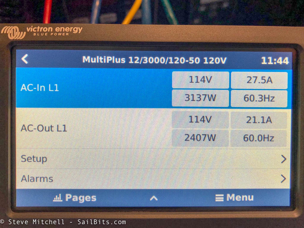
The visibility that the CCGX gives you into all parts of your system is really nice. Above you can see the AC power status including how much power I am pulling from shore side, the various voltages and Hz, and you can setup all sorts of specific alarms about this by just clicking a few buttons. Many other solutions have this info, but it is not as elegantly presented, and surely not as easy to configure and change alarms and settings.
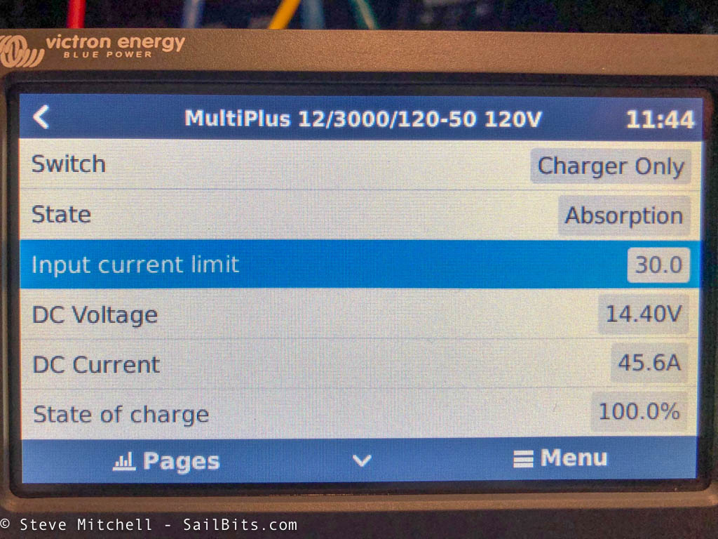
The inverter/charger can be controlled and seen here as well. Tons of additional features, alarms, and visibility.
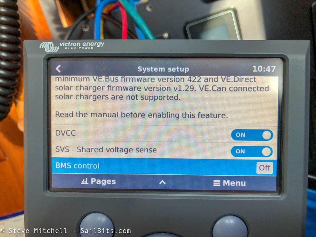
One thing that is important is to ensure that BMS control is “ON” if you are using the Victron BMS with LiFePO4 batteries. Here it is “Off” and you can’t turn it on manually – it has to detect the BMS, and I had to experiment with some off/on ordering with components to get it working.
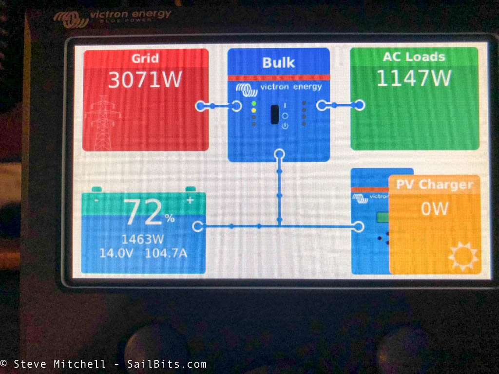
This is my top favorite screen because of how easy you can see everything from AC shore power, inverter status, how much AC power you’re using on the boat, battery status, and solar – plus the direction power is flowing. Tons of visitors who have seen the system can’t get over how easy it is to understand everything that is going on, all in one place.
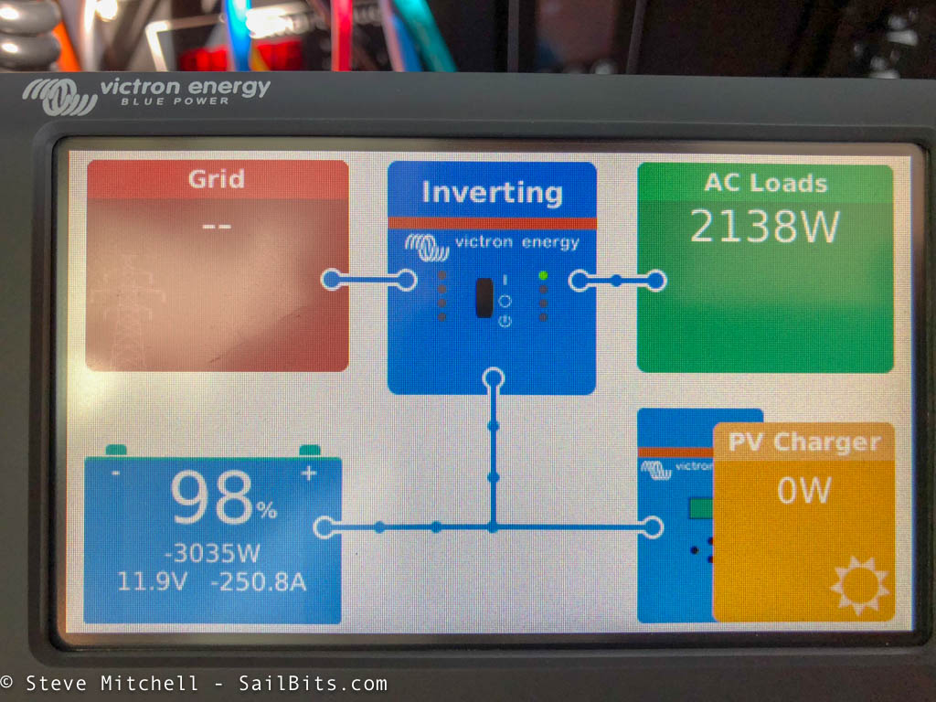
Here’s a great screen from when I was away from the dock and spun up my Nespresso coffee machine along with a few other devices which had the inverter working pretty hard. The fun thing is the sheer amount of amps (250!) coming from the 300ah LiFePO4 battery.
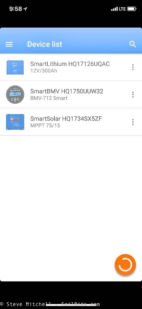
The other way to see status is by using your smart phone. Victron has an app that connects to various devices via Bluetooth – on Grace that would be the battery, solar controller, and battery meter. They show up when you scan for them above.
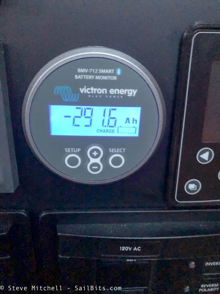
The BMV-712 battery meter is a great addition to any boat, not just one with LiFePO4 batteries. Not only can it monitor current (via the shunt), display state of charge, and voltage, but it can also monitor a second (start, other) battery bank, have a ton of different alarms, and share it all via Bluetooth. I also connected mine to the Color Control GX which is important for a whole monitored system.
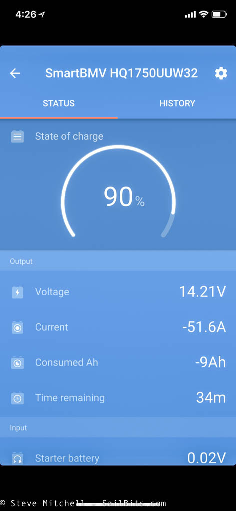
I use the BMV frequently when I was above decks, or in my stateroom for the night checking on things. I can see state of charge, current draw, time remaining (estimated) and other details.
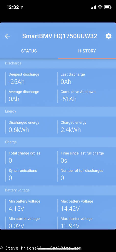
Each device has more detailed screens, and the BMV shows details around historical discharges, voltages, and the like.
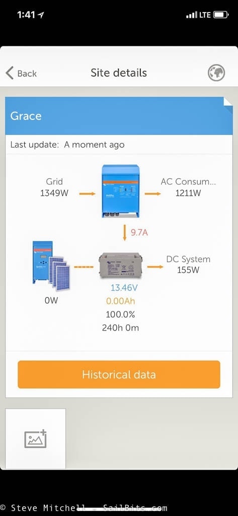
One of the best parts of the Color Control GX is the fact that you can set it up to send real time data to Victron’s Remote Management internet portal, if you have an always on internet connection. You can then get all sorts of awesome info on the portal via a web browser, or use a dedicated app for Android or iOS to see the information anywhere in the world!
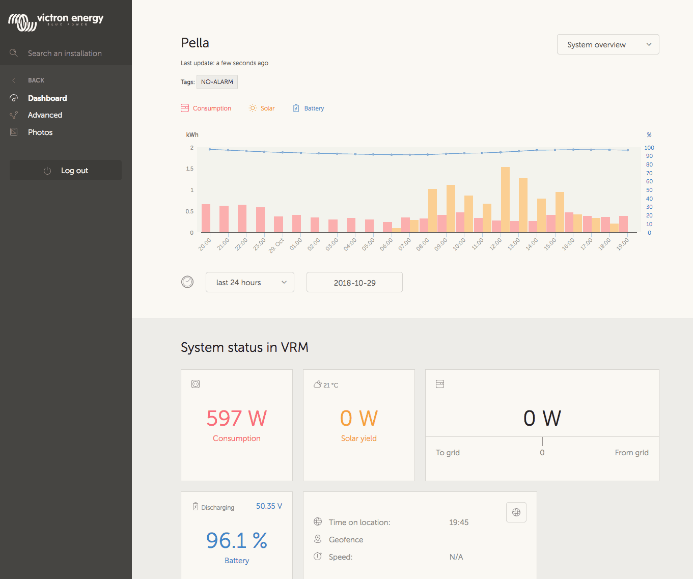
You can see a demo of the VRM system at https://vrm.victronenergy.com/installation-overview
Solar
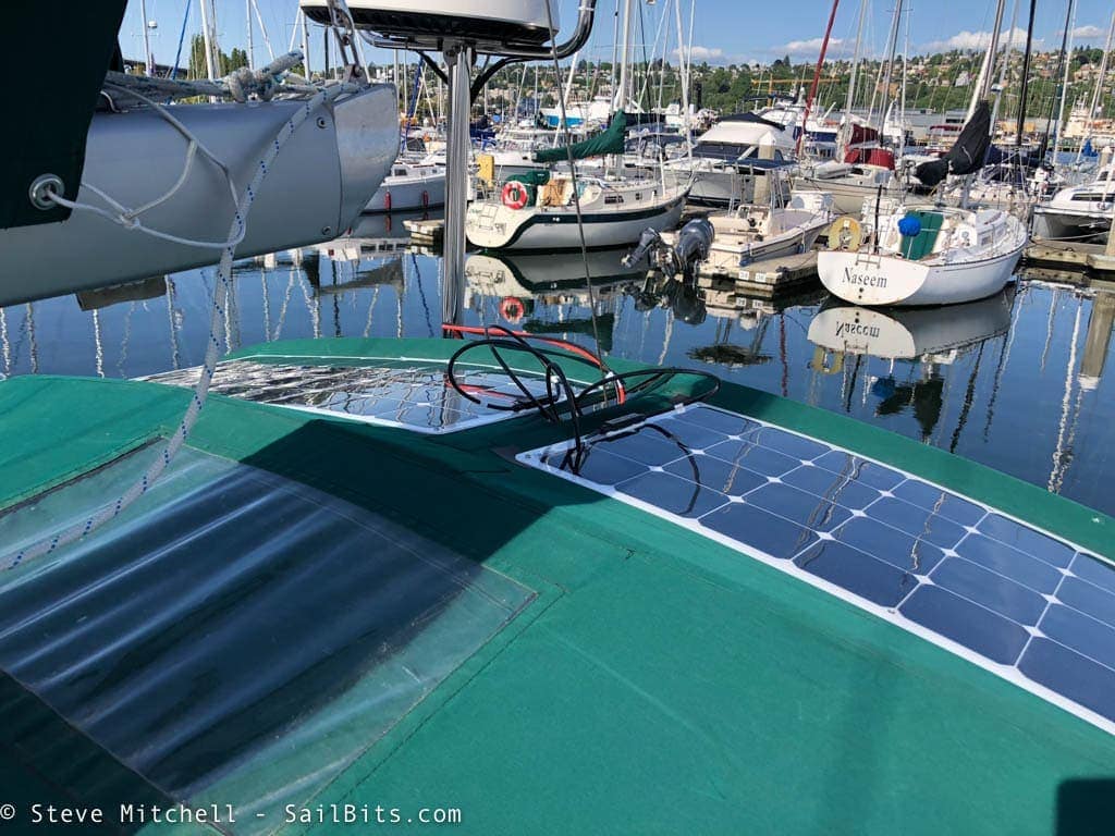
My solar setup was the simplest part of the system. I used a similar setup to S/V Violet Hour who made it look so simple, I decided I could do it too! I ended up purchasing two 100W flexible panels and mounting them on the top of my bimini the same way they did.
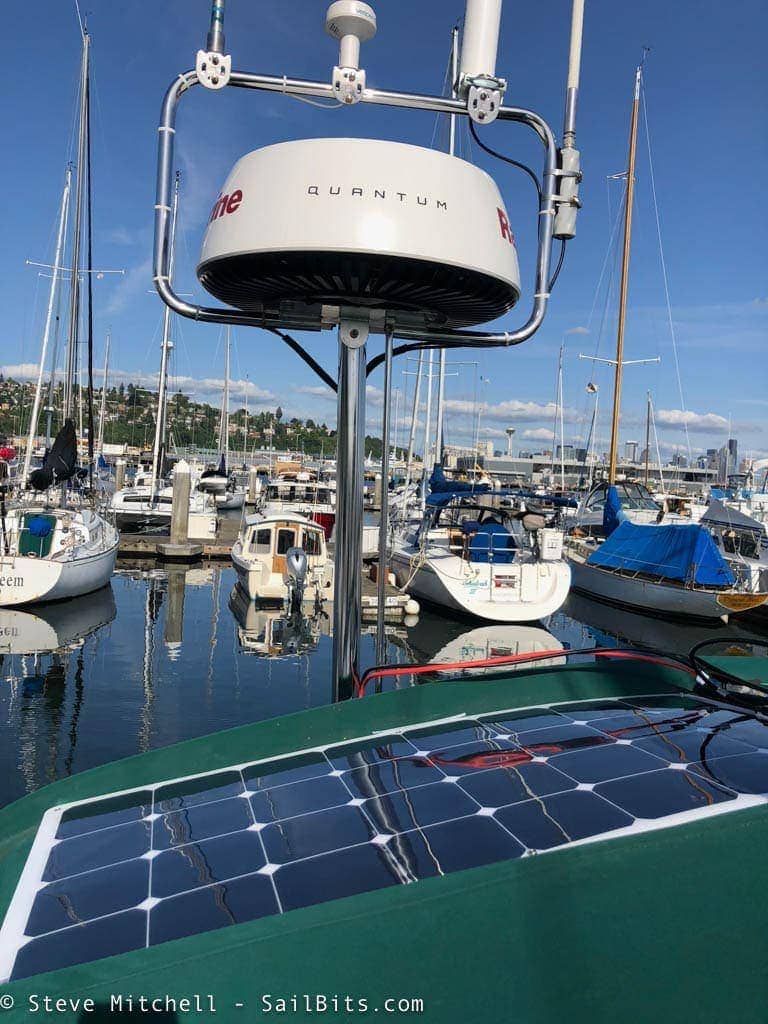
I ran the cables down the radar pole and into the lazarette, and then to the Victron MPPT 75/15 solar controller. I connected the controller via Victron’s VE.Direct cabling to the Color Control GX so that it could adjust parameters and provide all of the data on the displays and online.
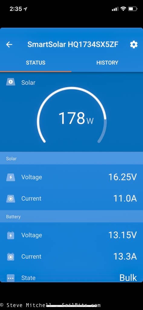
The MPPT solar controller has a Bluetooth radio in it, and you can use the same Victron app to configure and see what is going on. I saw absolutely amazing performance from the controller and panels multiple times throughout the summer – above you can see I am getting 178 watts out of two 100W panels – that is pretty amazing overall results!
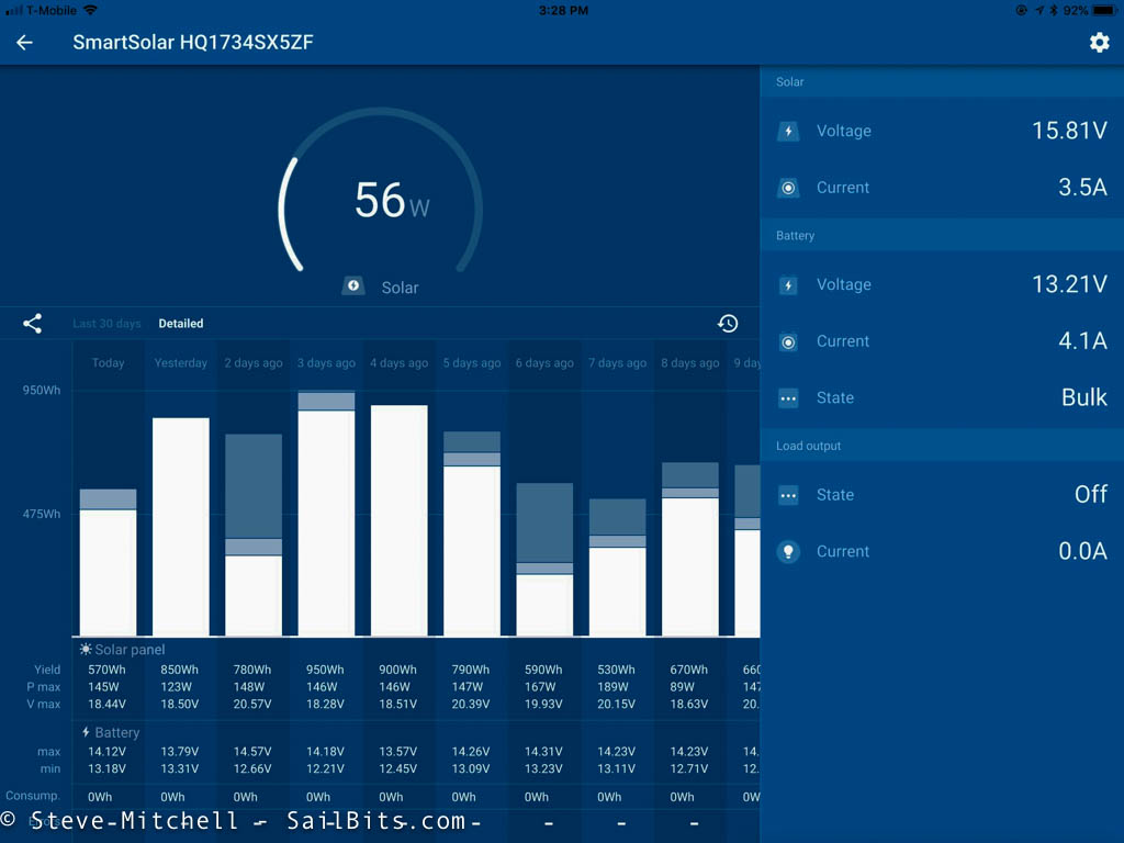
Using an iPad with the same app, and you get a much nicer layout. This was one of the weeks where I got absolutely phenomenal performance out of the solar system – check out that 950Wh number!
Testing

I did extensive testing with this system both as I built it, once it was completed, and on 15 different trips this year in all sorts of conditions. However, the most important tests that I conducted were both over charging and full discharge scenarios. I wanted to ensure that all of the BMS settings, relays, and other pieces worked exactly as they were supposed to. Having either of those situations with a LiFePO4 battery could damage or destroy it, which is an expensive mistake.
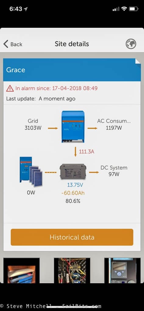
I also monitored my testing via the iOS app both locally and remotely, and configured many alarms and thresholds to ensure I would be alerted in as many ways as possible to something bad going on.
The over charge testing was pretty easy to do, and the BMS disconnected the charge sources (solar, inverter, alternator) as soon as those conditions were met. In fact, this happens a lot when underway after just leaving the dock with a fully charged battery.
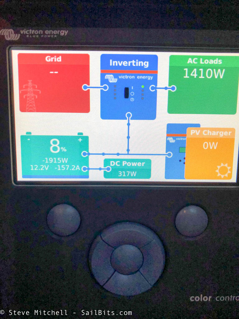
Full discharge testing took a bit longer, as I actually had to drain the battery. I ran the boat without dock side AC power for most of the day, and added various small and large loads to get down as low as possible.
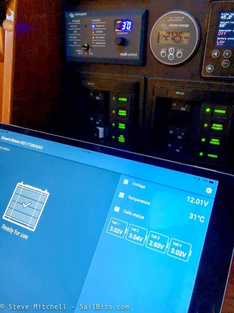
During the testing, I was logging everything locally on paper, monitoring the battery and battery meter via Bluetooth apps, and of course the Color Control GX was sending the data to the online portal. However, at some point, the DC house loads and everything else will go off to protect the battery, and the internet logging will stop – the CCGX will queue that data up and send it up eventually, but there will still be a gap as the CCGX goes off. In the picture above you can see the cells in the LiFePO4 battery getting lower, and in the background, the battery meter showing a total of 272.5 amp hours used so far.
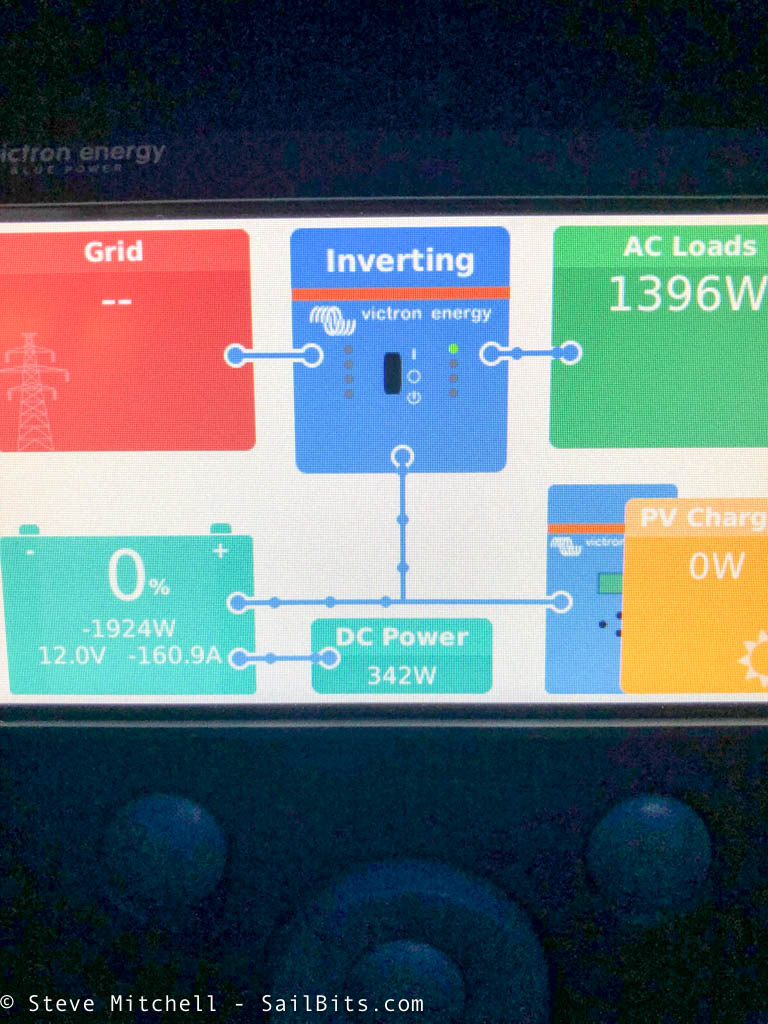
It is always a bit disconcerting to see 0% battery left – it took some getting used to that LiFePO4 can be discharged much further than a standard AGM or flooded setup.
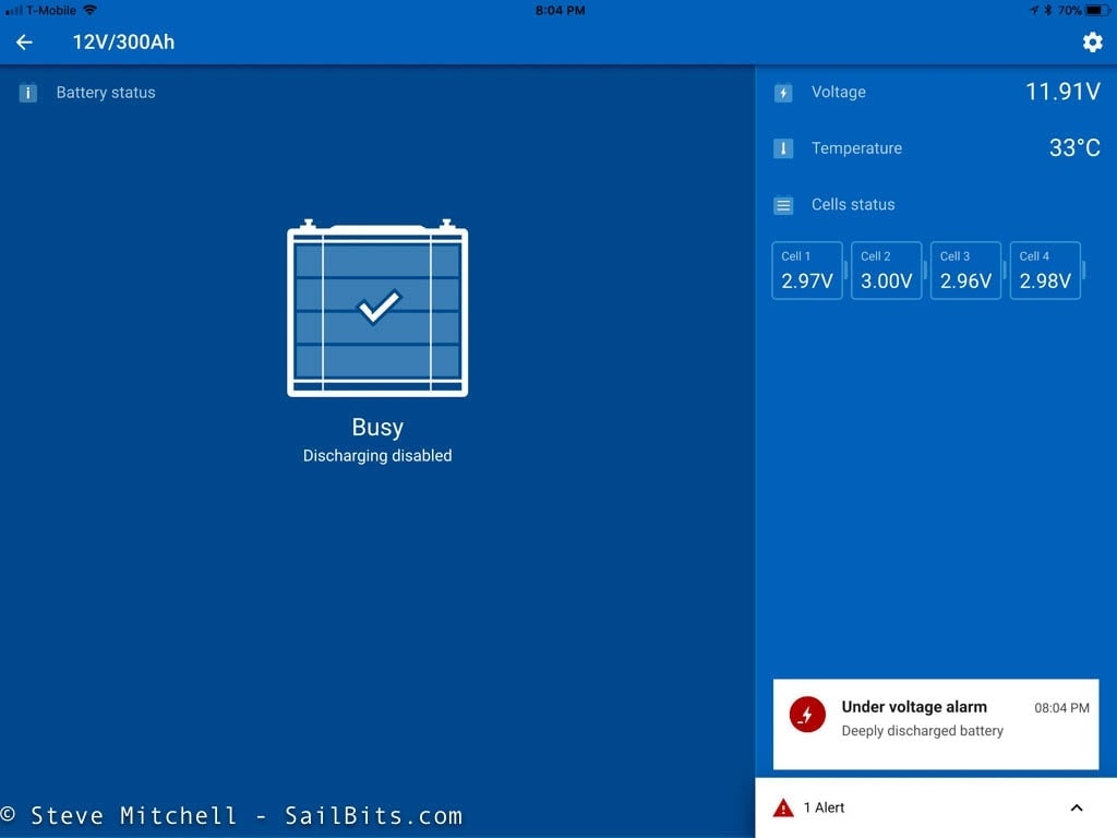
Finally, once one of the cells in the battery reached the low point, the BMS shut off all DC load relays (house loads and heater) and the Bluetooth app showed an “Under voltage alarm” and that the battery was “Busy” – discharging disabled!

Total amp hours used from the 300 amp hour LiFePO4 battery was 291.6. That is pretty darn impressive! I only did this once to validate that all of the relays and systems shut things off – its important to ensure that happens or you could completely destroy your battery. After the testing, I setup alarms and alerts to go off around 20% left of battery capacity which would alert me both locally and remotely. That seems like a good point to intervene if things continue to discharge.
Using the System
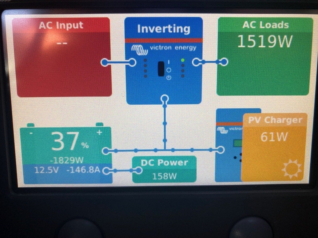
Making coffee with my Nespresso machine after 2 days on the hook at Blake Island in June
I used this system at the dock tons of times just for fun and testing both connected and disconnected from AC power. Everything worked flawlessly, and was actually far less work to use than the previous systems. But I also used it on a bunch of trips this summer.
Random Trips
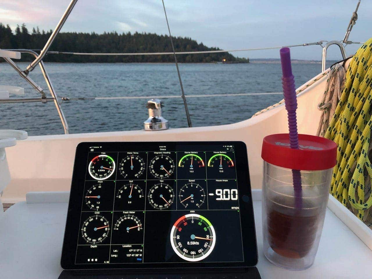
Using WilhelmSK on the iPad, getting data via SignalK + Victron plugin. This was on a solo trip to Eagle Island in south Puget Sound
I took various trips lasting from a single night away from the dock, up to a 5 day trip with only solar and alternator charging. All told, I had over 25 nights away from the dock with the system running perfectly.
There were even more trips where we never really drew the bank down that much due to the high capacity alternator keeping things topped off during the day.
Princess Louisa Trip
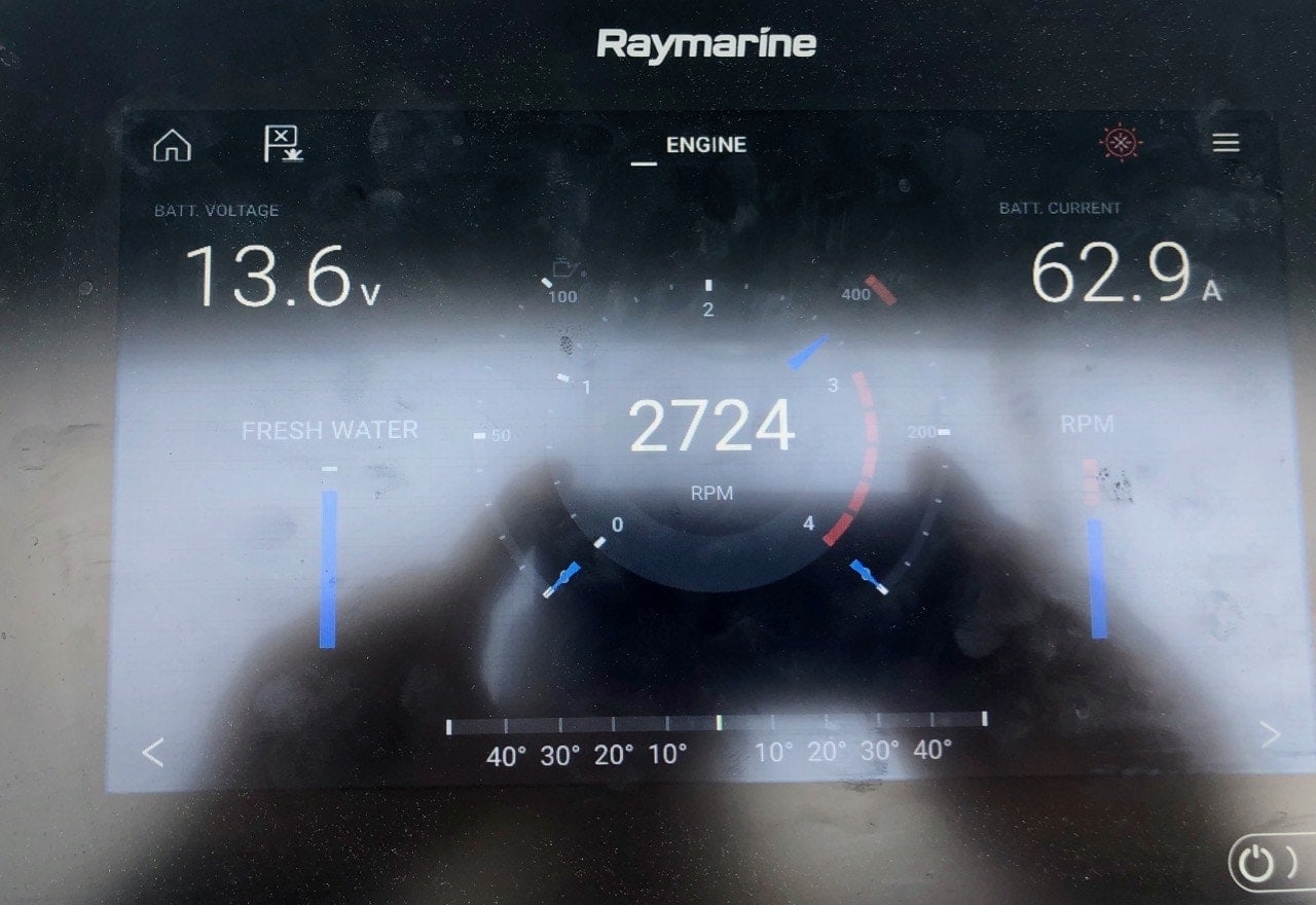
Charging via the high amperage alternator while motoring back from Princess Louisa Inlet
The longest and biggest test was my 18 day trip to Princess Louisa Inlet. Not only were there many nights away from the dock on the hook, but long distances, shaded sunlight in the inlet from solar, and many demanding loads on the system for the entire trip.
I started not worrying as much about power as I had in the past as the system was actually designed to work as reliably as possible without much user intervention.
Conclusion
A LiFePO4 based electrical system is definitely the cutting edge if you can afford it. The ability to discharge the battery so deeply, quick recharge times, and high amperage discharge rates are all great for a boat with moderate to high electrical needs. The reduction in weight and size is a huge plus for a sailboat.
But this sort of system comes at a cost – both in dollars, and in complexity of installation. Having to put relays and limiting circuits in place to protect the battery, all controlled by a battery management system is not typical for boat electrical systems, and if skipped, can be a costly mistake.
I think the benefits of the deeper discharge rates, less weight, more overall cycles and higher performance is well worth the investment.
Archived Comments
These are read only comments from the old system. Scroll down to participate in SeaBits Discussions, our new interactive forum attached to each article.
Lee Scott
January 21, 2019 at 5:44 pm
What was the total cost of the system – wiring, battery and electronics?
- Steve Mitchell
January 21, 2019 at 6:50 pm
Good question. I had to back and find my planning spreadsheet with all of the parts, and compare that to what I actually ended up purchasing. It was just a hair over $7800 for the whole system, including wiring and ends. Keep in mind though that I did all of my labor (including the wires and terminating) so that could drive the cost up considerably if you don’t do that work yourself.

