My ongoing solar project at our family cabin in Eastern Washington took a simplification turn this last weekend. Much of what I’ve learned rewiring boats and working on DC systems has helped me fine-tune this installation, and it will be helpful when working on and installing solar systems on my sailboat.
In October 2015, I had tried to adjust my system to be more reliable and add some functionality. Since then, I’ve made some major changes and compromises.
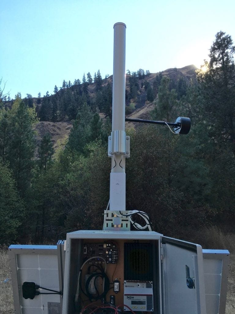
WiFi Antenna and Access Point as of October 2015
The first big change, which happened a few months ago, is that the WiFi antenna and access point were removed from the installation altogether and moved to an outbuilding much closer to the house where there was normal AC power. The power demands from the AP paired with the high power antenna were too much for the solar panel and 110 amp hours of battery capacity. The long term plan requires this be moved back at some point, as the wifi coverage down to the river is only possible with the antenna sited somewhere near this spot.
I believe the only solution is to invest in a larger battery bank and place it in a ground-mounted storage container. I hope to look at this in early spring 2017 since the winter and fall months are not fun to do ground things here.
I also shut off the RMS-100 linux machine that was responsible for turning on and off loads and monitoring current usage and other things via SNMP. It had never been 100% reliable at doing things in the automated fashion it was billed to do, and it took up a decent amount of power just being on.
This left the battery bank, associated cabling, DC to DC converter, and the Dropcam. For the last few months this has been running perfectly with no outages or issues. The Dropcam was set to stop transmitting video at sunset and to resume at sunrise, thereby reducing the overall power usage as much as possible.
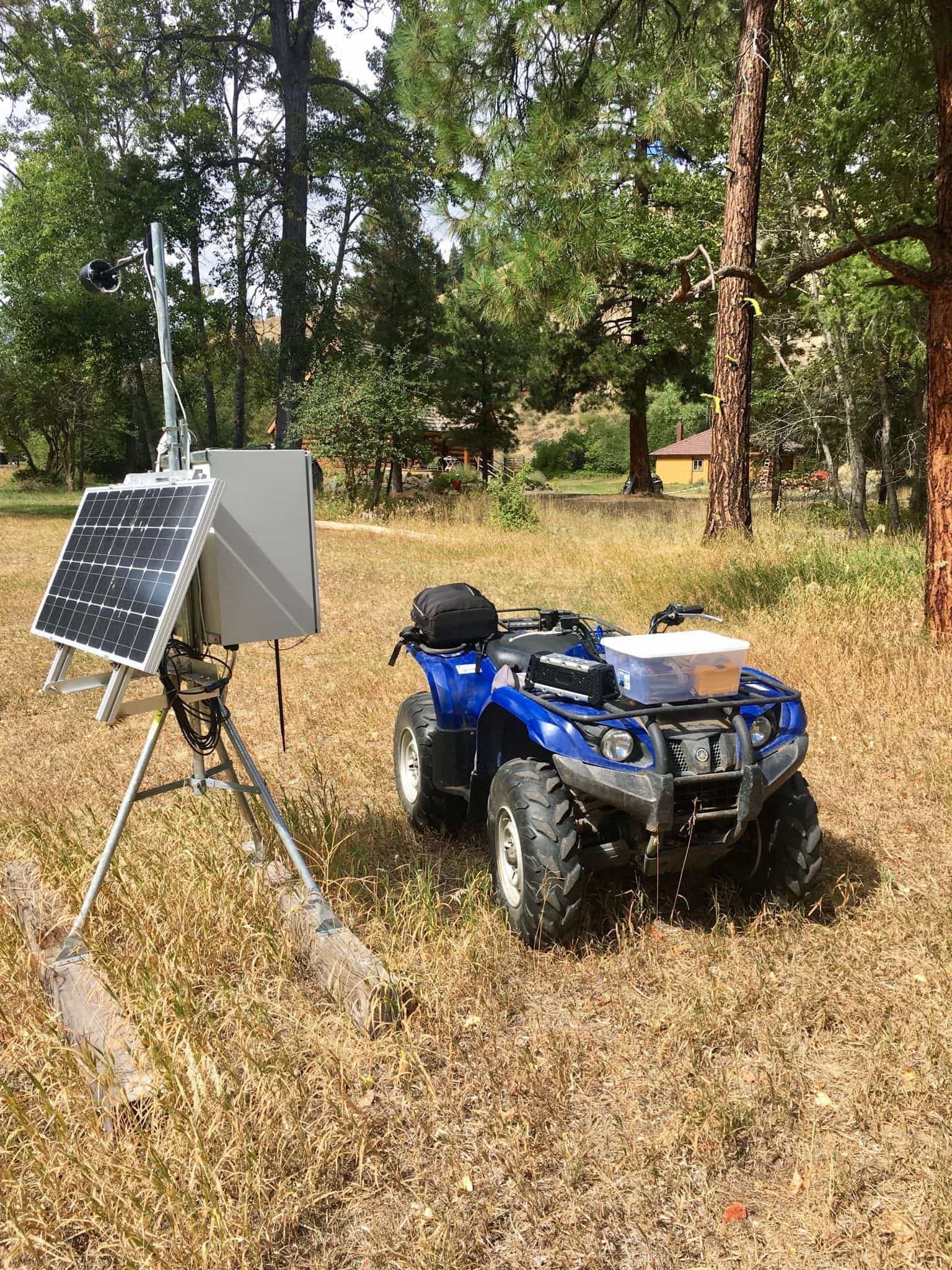
My work bench at the solar panel location
While things were working well, I still wanted some sort of monitoring on the battery voltage, solar effectiveness, and more. Since I have been throwing Raspberry Pi’s everywhere for random different tasks, why not here?
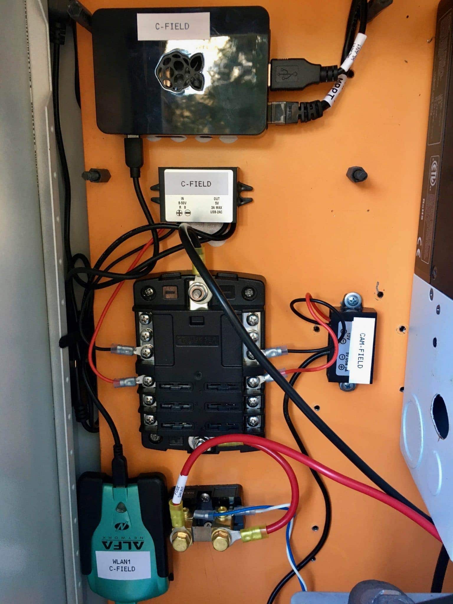
Raspberry Pi and associated bits in the box
The design was dead simple. The MorningStar MPPT solar charge controller has an ethernet port and IP address that I had been using prior to this with the WiFi AP to gather stats. I was going to use the Raspberry Pi to bridge the two together. The Pi would have a WiFi card and connection to my existing network, and then use its ethernet port to connect to the MorningStar. Using IP forwarding, I could have the Pi route the traffic destined for the MorningStar directly to it, acting as router for a single host. Adding a static route at my main router ensured that I could directly access the MorningStar from any machine on my network.
The parts list is pretty short:
- Raspberry Pi 3 Model B – I prefer the CanaKit bundles for the extras they come with
- Alfa high gain USB wifi adapter – good for long range stuff. Used before on the boat.
- Alfa 9dBi magnetic antenna – to connect to the above
- DC-DC buck converter – to convert 12V DC battery power to 5V for the Pi
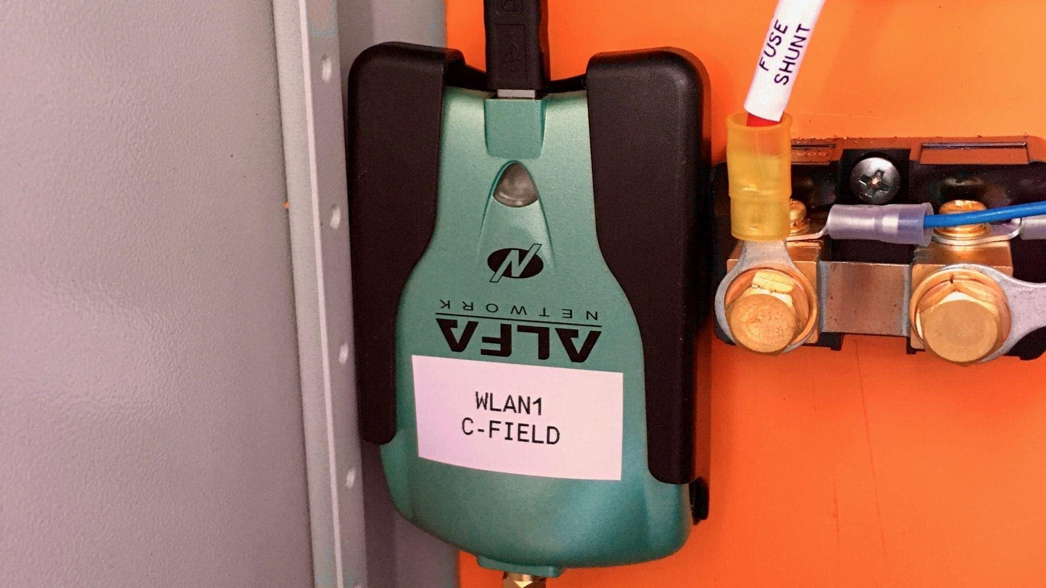
Alfa long range USB wifi adapter
I’ve used the Alfa network adapters in the past on the sailboat while boosting remote WiFi signals to a computer or two. They also used to be part of The Wirie product that I owned on Jammy years ago, and have always impressed me with their power. I paired this one with a magnetic 9dBi antenna that I planned on sticking onto the big fancy metal box everything was installed inside of.
I chose to do this instead of using the built in wifi both for reliability and signal strength issues. The box the Pi is inside is quite thick steel, and I doubt the built in chip could reach the AP over 300 feet away. I’ve also had a ton of issues with the Pi 3’s and their wifi chips, some of which have been resolved in recent firmware updates, but not all.
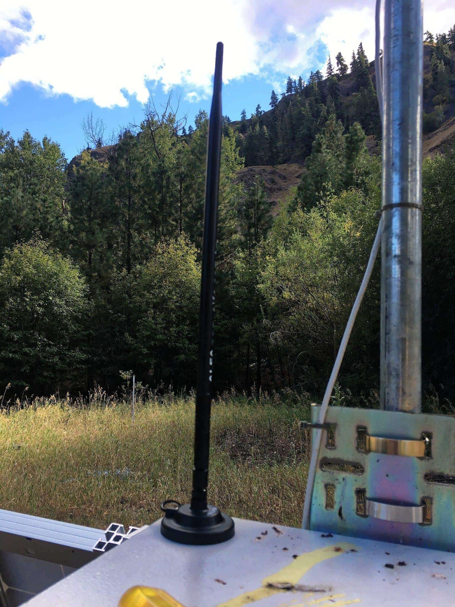
Alfa 9dBi antenna
The antenna lead was a perfect length, and the magnet feels like it will keep the antenna in place through most weather. The signal strength measured at both the Pi and the AP looks good, and connectivity seems reliable for the last week of use.
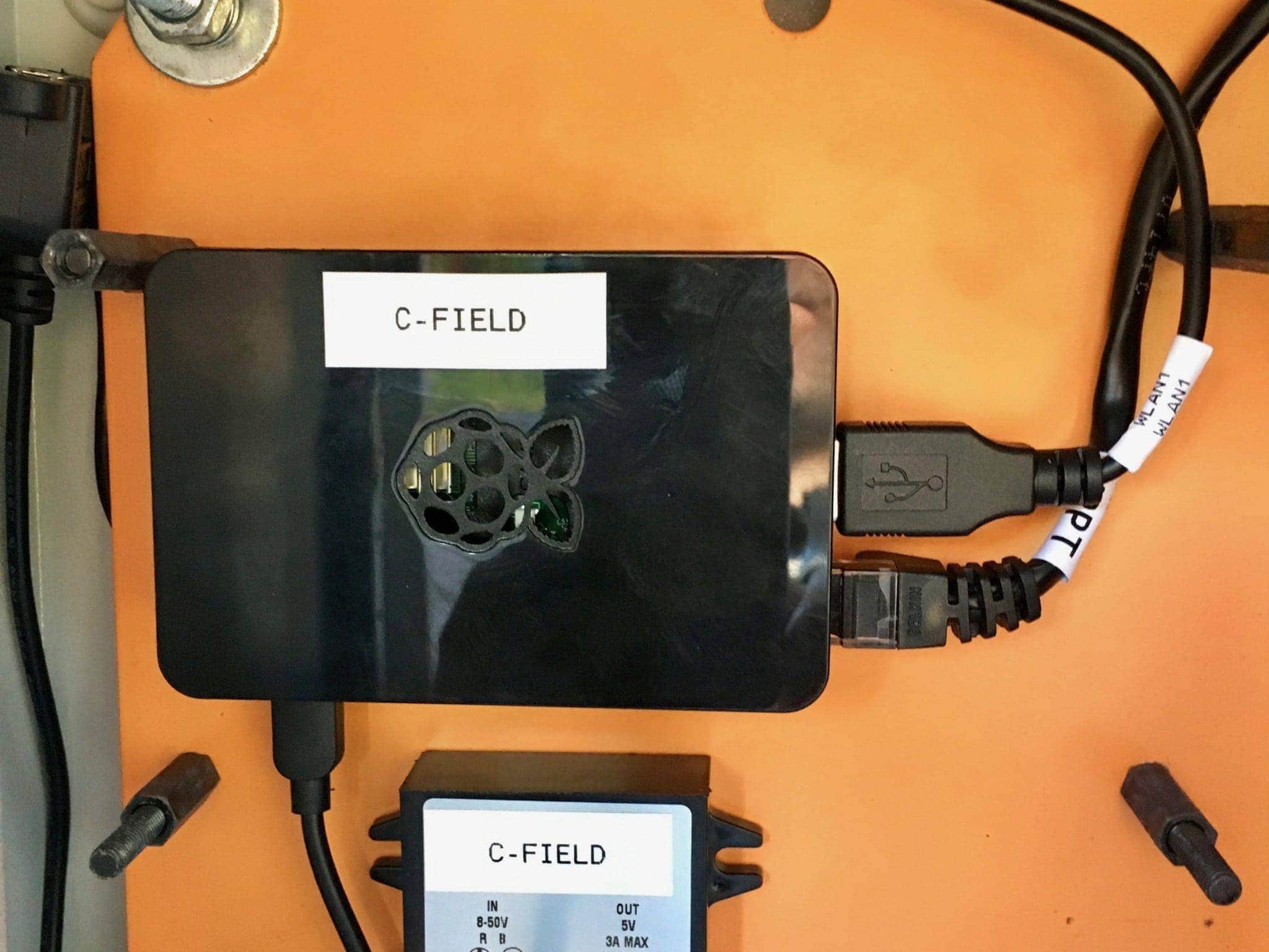
The Pi has only a few connections – power, ethernet to the MorningStar solar controller, and USB to the Alfa WiFi adapter. The nice thing about the Alfa is that it didn’t require any special drivers, and worked right out of the box.
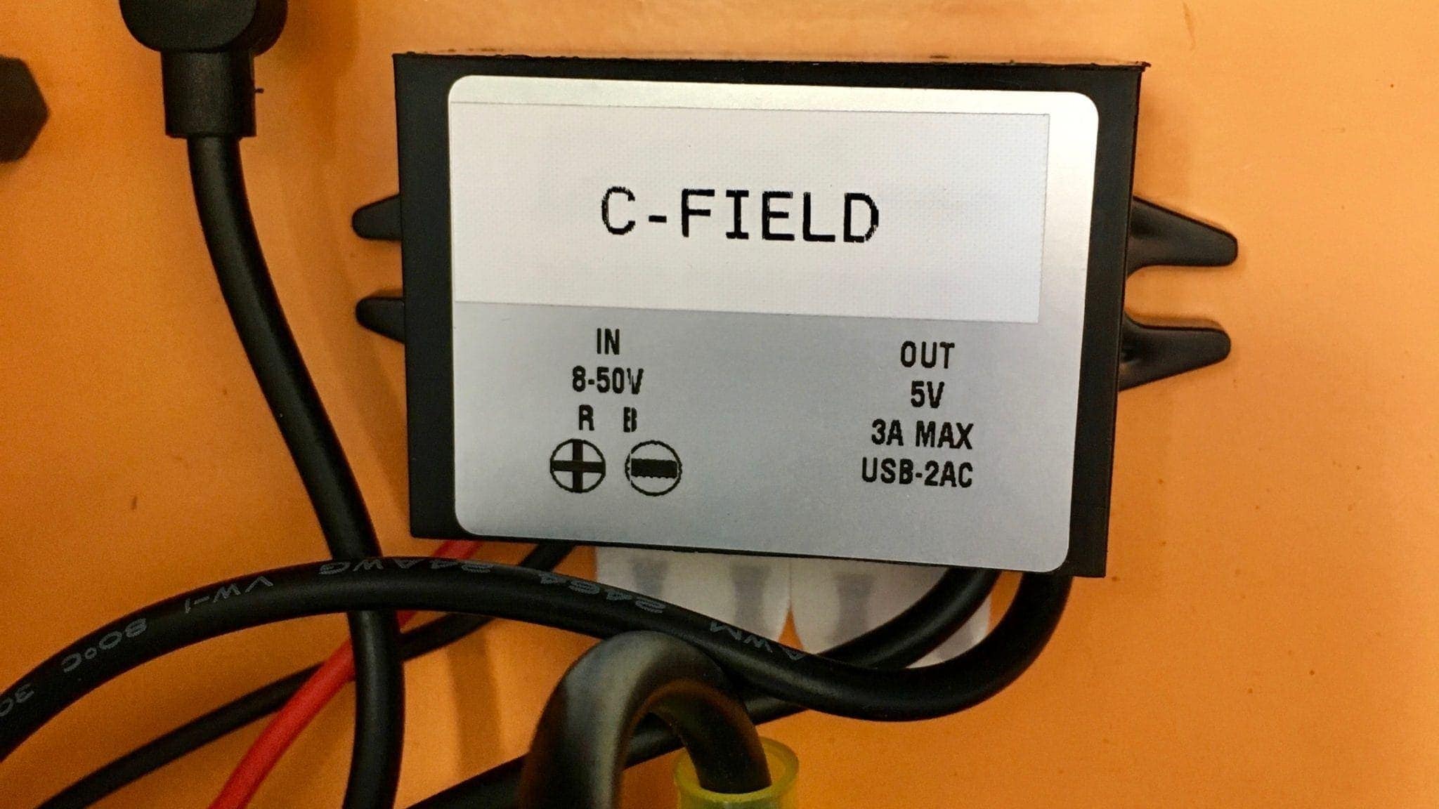
DC to DC buck converter
The Pi gets its power from a DC to DC buck converter, which I’ve used in a number of applications. This one can take anywhere from 8-50V and spit out a constant 5V USB-quality level voltage on the other end. This particular model has two USB ports, which I thought might be handy for plugging in something else in the future. It also has a max of 3 amps, which is more than enough for the Pi. I’m not sure how efficient these are, or if there is a better way to do this from 12V to 5V, but many people seem to use them, so here I am.
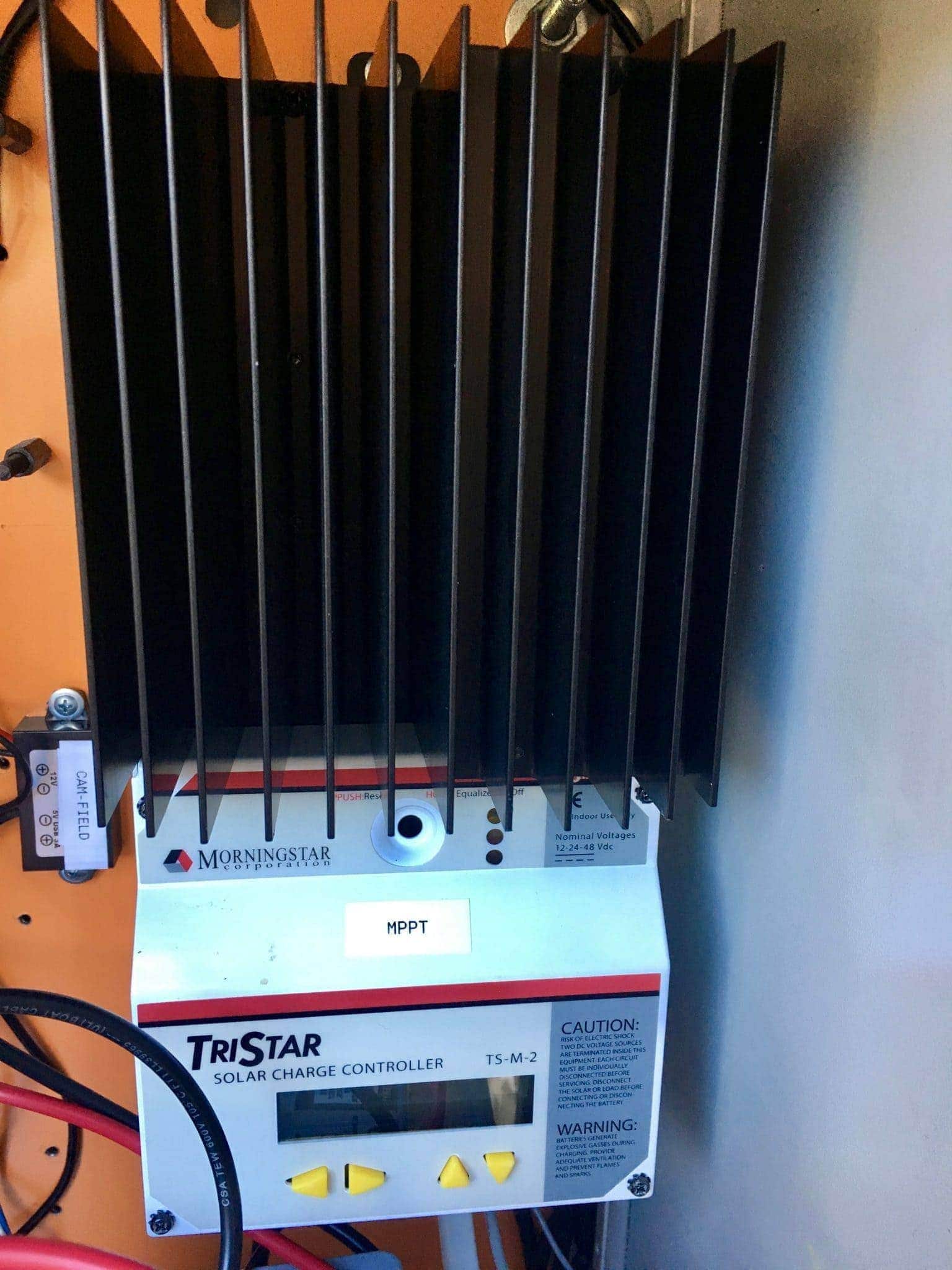
MorningStar TriStar MPPT solar charge controller
The real brains of this whole operation is the MorningStar TriStar MPPT Solar Charge Controller, which I’ve written about before. They come highly rated, and I have nothing but good things to say about them. I have the 60 amp model with the front LCD panel, which is not included in the base model. The base model does come with an Ethernet port, but is very hard to configure without the LCD panel.
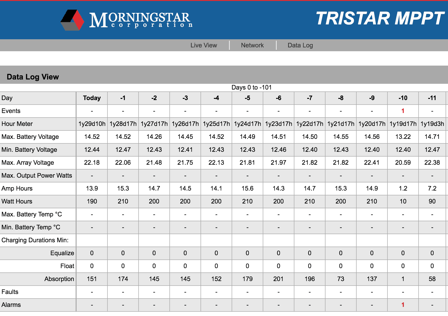
MorningStar TriStar data log
The MorningStar has a simple web interface that shows you current status as well as a data log, allowing you to see the performance over time. Note that on day 10 above was my install, and the whole array was down for a large portion of the day, hence the low numbers.
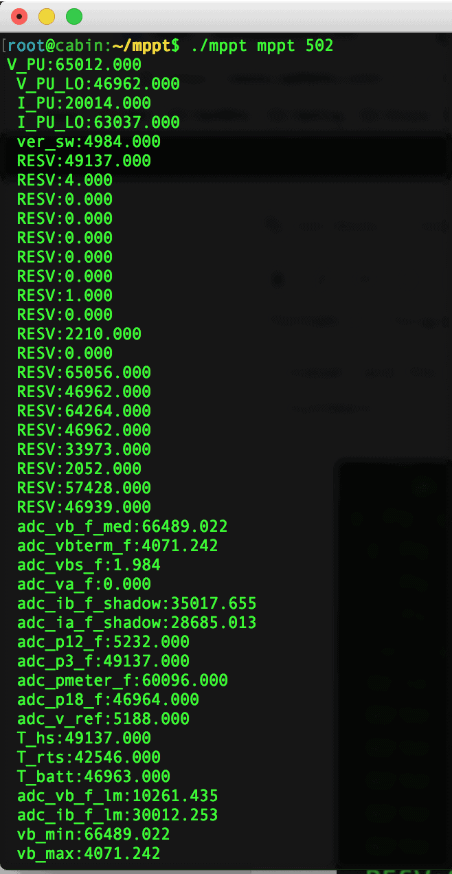
Modbus query to MPPT controller
In addition to the web interface, there is a modbus interface exposed on the controller, and I found someone who had parsed the values and written a simple C program to display them. Unfortunately it looks like the original link has moved, and there is new code/examples but in Spanish.
I wrote a set of scripts to stuff this information into an RRD after querying it via Modbus.
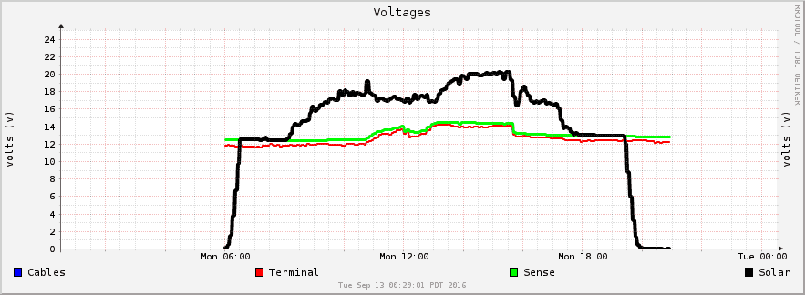
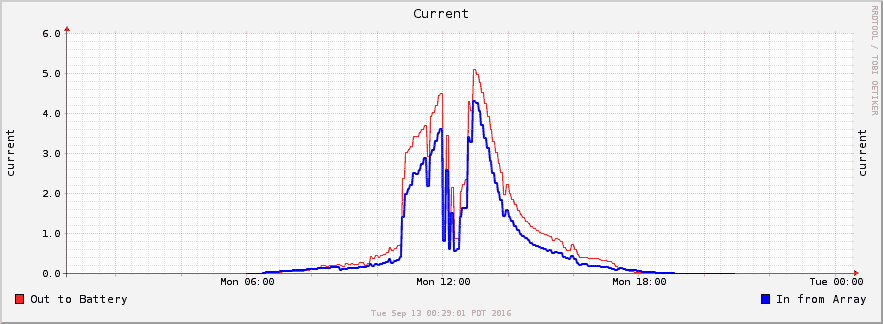
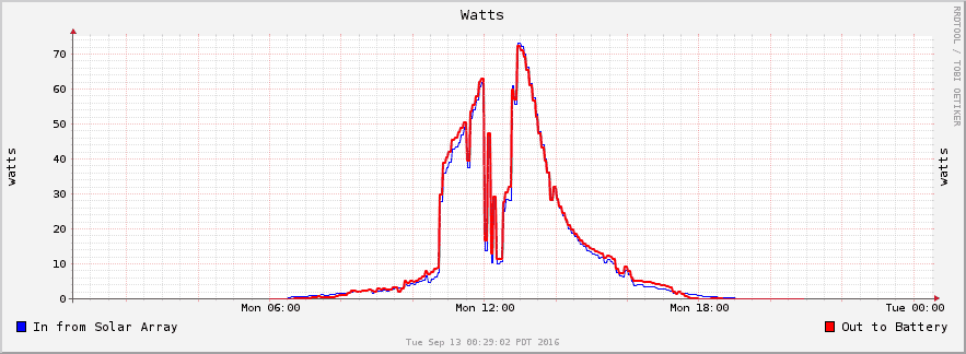
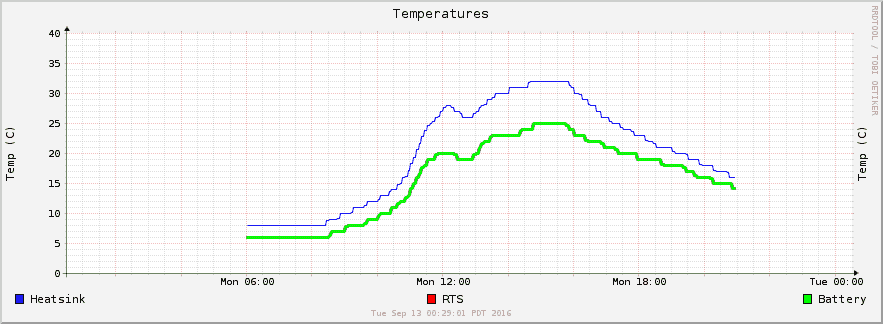
The result is a set of graphs that allow me to see real-time performance of the array during the day. And because I’m using an RRD, I can generate graphs over a much longer time for averaging and more. Note that I have the querying stop at sunset, and resume at sunrise to save on power/queries.
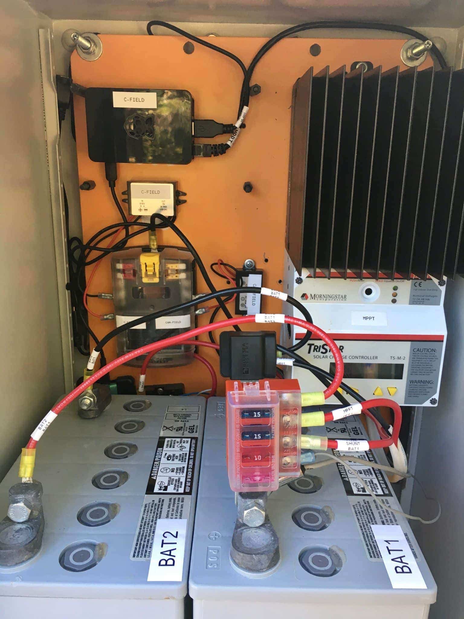
The overall install is much simpler than before, and seems to be holding up well after a week of data gathering. I’m using a BlueSea blade fuse panel for the DC loads, and a battery mounted blade fuse setup in the foreground – all marine-grade. These were left over from my home NMEA 2000 network that I don’t use anymore, and I decided they were more than good enough for a solar install.
The next enhancement I want to make to this setup is a current and voltage monitor for the Pi. I’ve found a few solutions out there that are standalone boards that can do a multitude of things. My goals are to be able to leverage the shunt (in the pictures near the top of this article) to monitor the amperage being used, as well as monitor the actual voltage at the batteries and solar panel.
So far, this simplified setup has worked great, and allowed me to get good data on the performance of the system without using much power. Only time will tell if this is the final configuration, although I suspect I will always be tweaking this one!


