A few weeks ago I posted about redesigning the nav and electrical panel, and after a lot of planning and discussion, I made my final choices, placed orders, and submitted my front panel to be made. A week later everything arrived, and it was time for an epic weekend project to remove the old one, and put the new one back in.
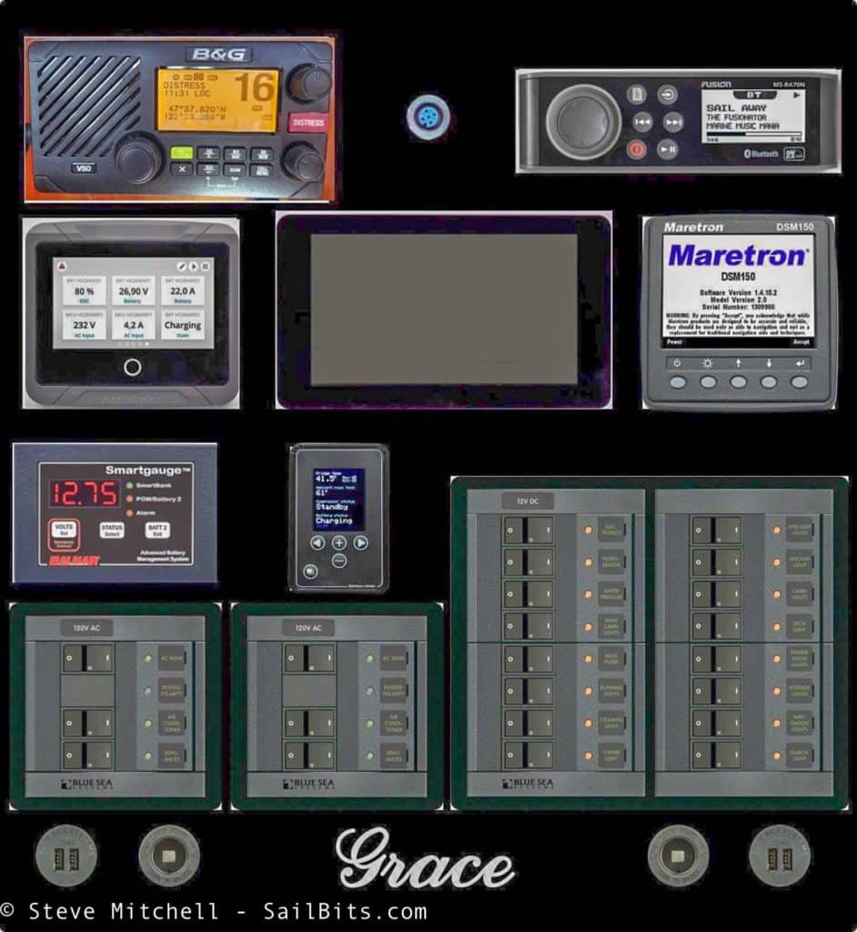
I always lay out anything I do in OmniGraffle to make sure things fit and look right. For the front panel, I exported the draft panel out of Front Panel Designer, imported it into OmniGraffle, and then added measured graphics for each item. The above is one of the last iterations of the panel I created before finalizing the layout.
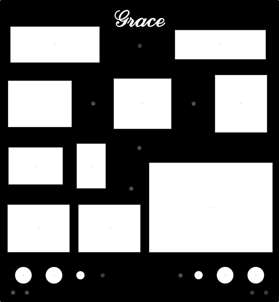
This is the exported final PDF from Front Panel Designer that I sent to Front Panel Express to be manufactured. You can see a couple of changes from the OmniGraffle layout, mainly the name at the top, and shifting some things up a little bit.
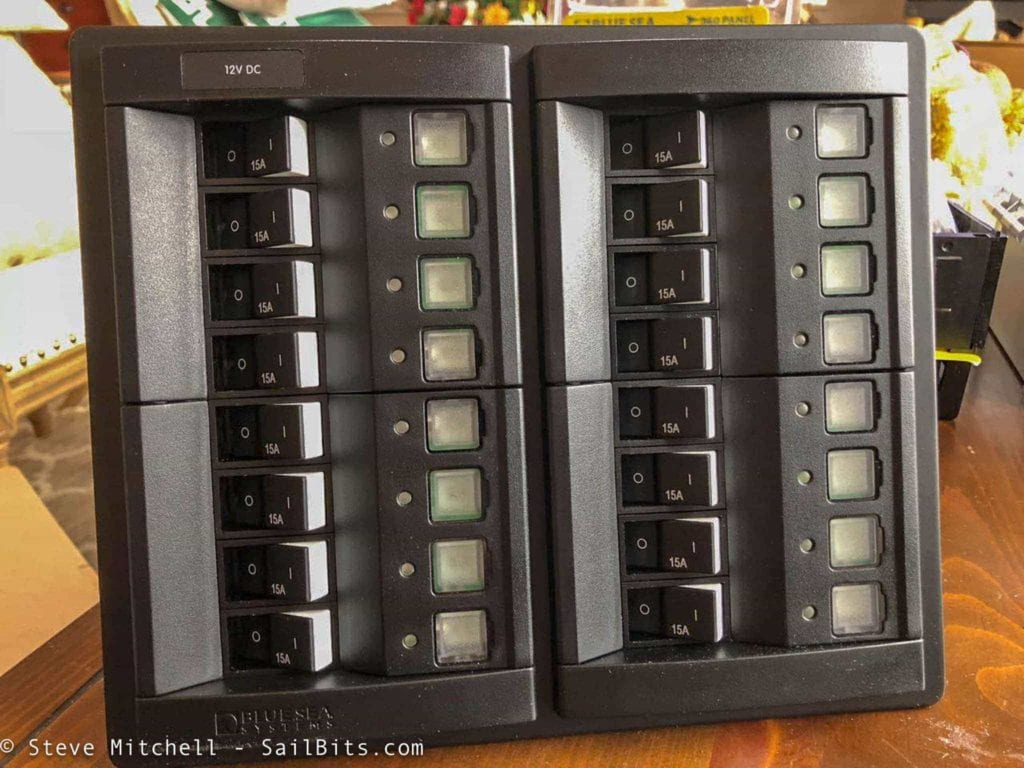
The biggest choice from my previous post was what type of AC and DC panels to use in the redesign – BlueSea 360, BlueSea Traditional, or CZone digital. After pricing out all three, I was able to eliminate the CZone solution, which was almost 3x the cost of everything else. While it would be great to control everything via software, it wasn’t worth the cost.
I ended up choosing the BlueSea 360 panels because of their compact size compared to the traditional panels. I couldn’t make the traditional panels fit the way I would like without displacing other instruments, and I had used the 360s before with my previous boat Jammy.
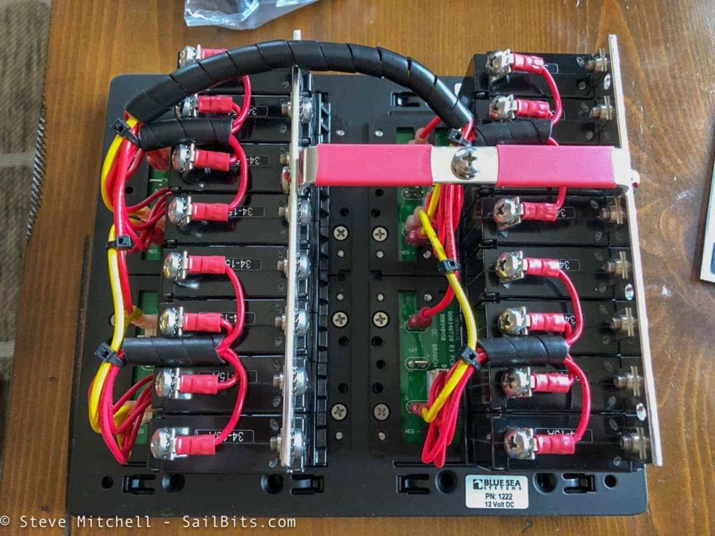
Both DC and AC panels come pre-wired with 15 amp breakers. I ended up with a 16 breaker DC panel, and two AC panels with a main breaker and two sub-breakers each.
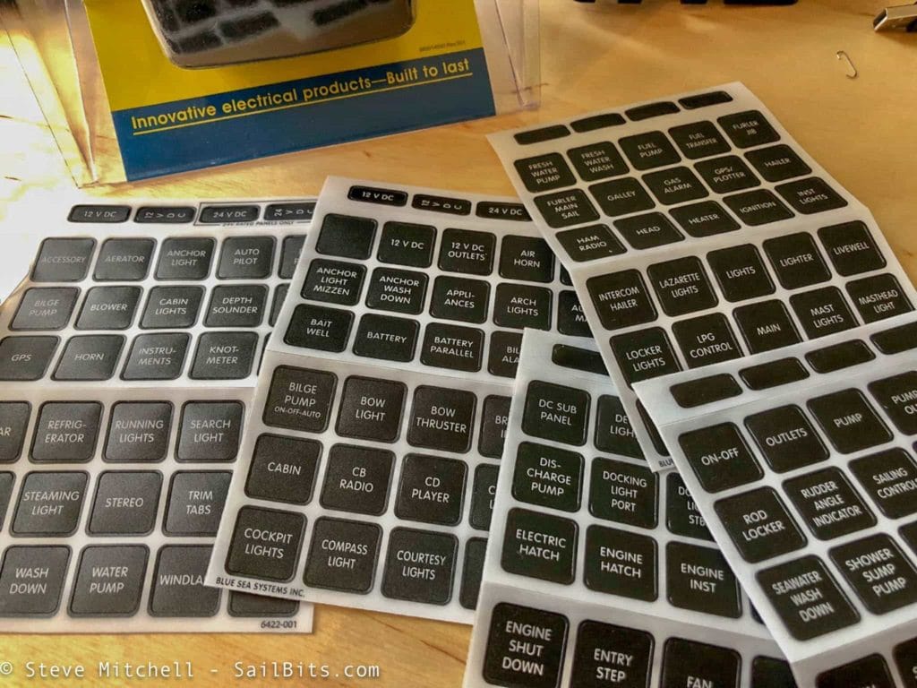
I also ordered some extra label kits to cover the various circuit names I knew I’d need.
A week or so after submitting my panel to be made, it arrived in very secure packaging.
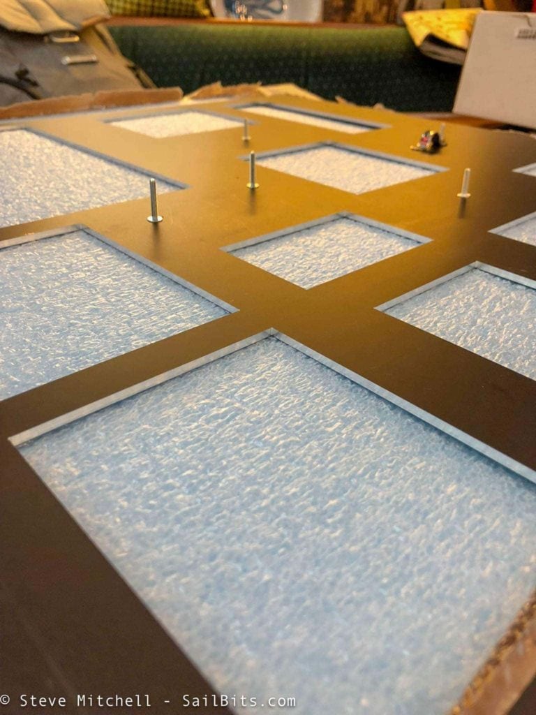
The back of the panel looked perfect as I removed the packing material. The accuracy and cleanliness of the cuts always amazes me – the shadows and reflections in the corners of the cutouts are perfect.
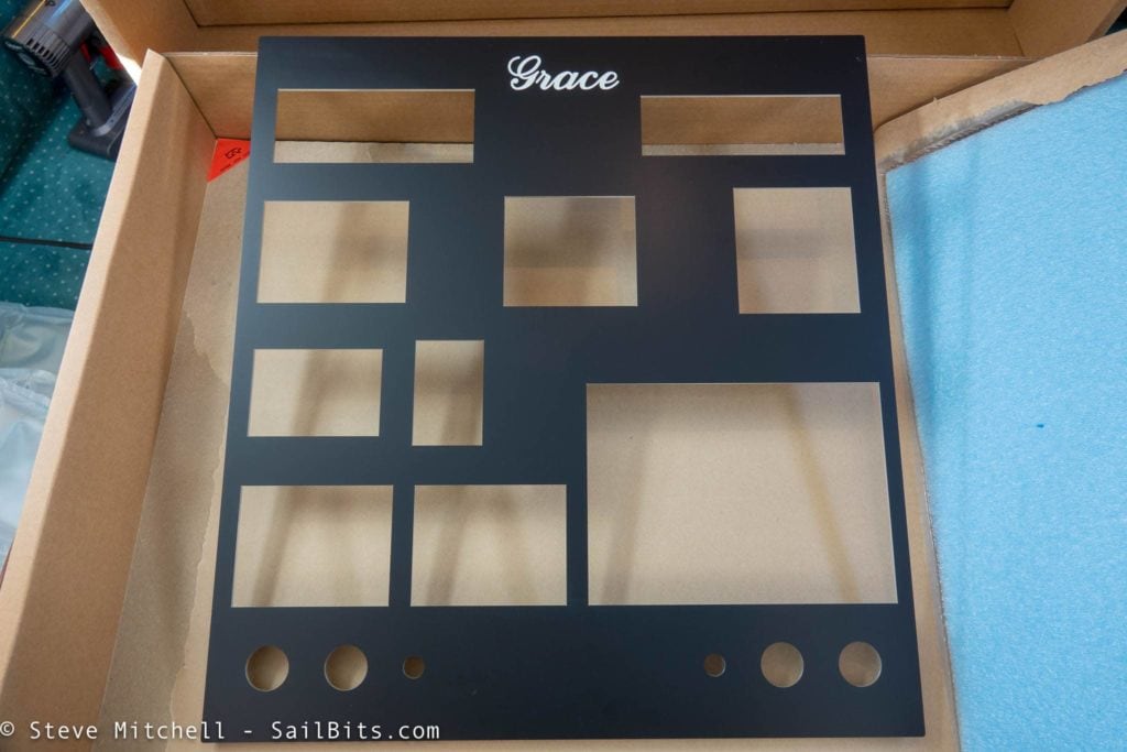
From the front it looked even better.
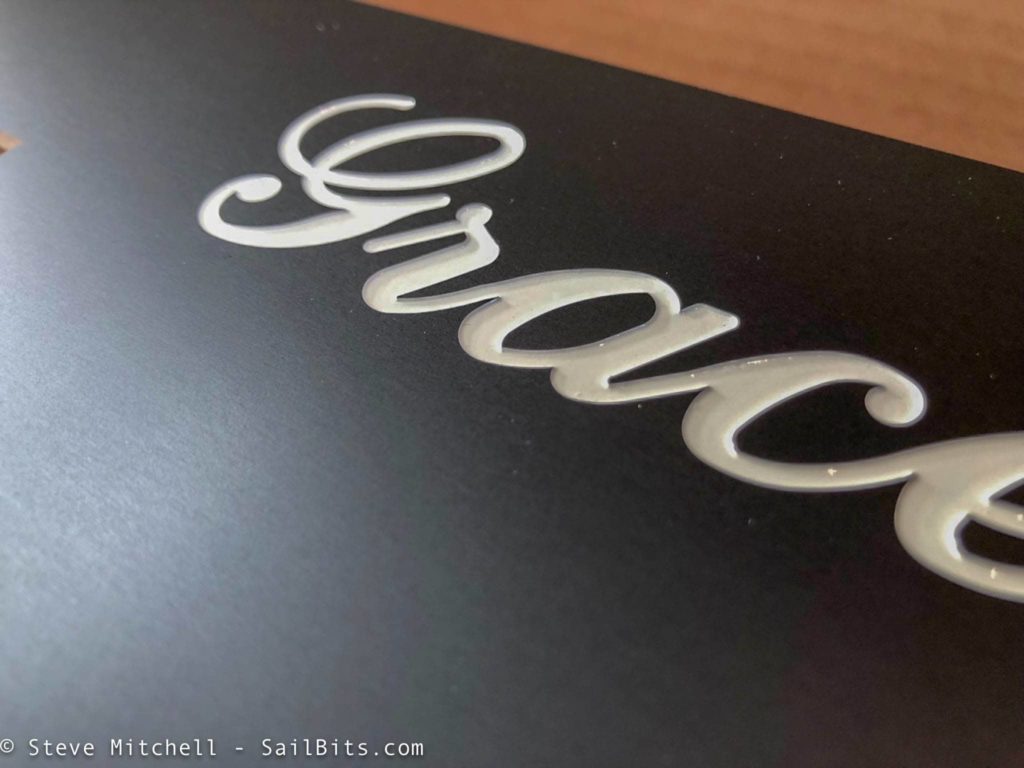
The inlaid name was a thing of beauty – they cut it out with their fancy machine, and then put the color of infill you request, and it has a 3d quality to it. Beautiful!
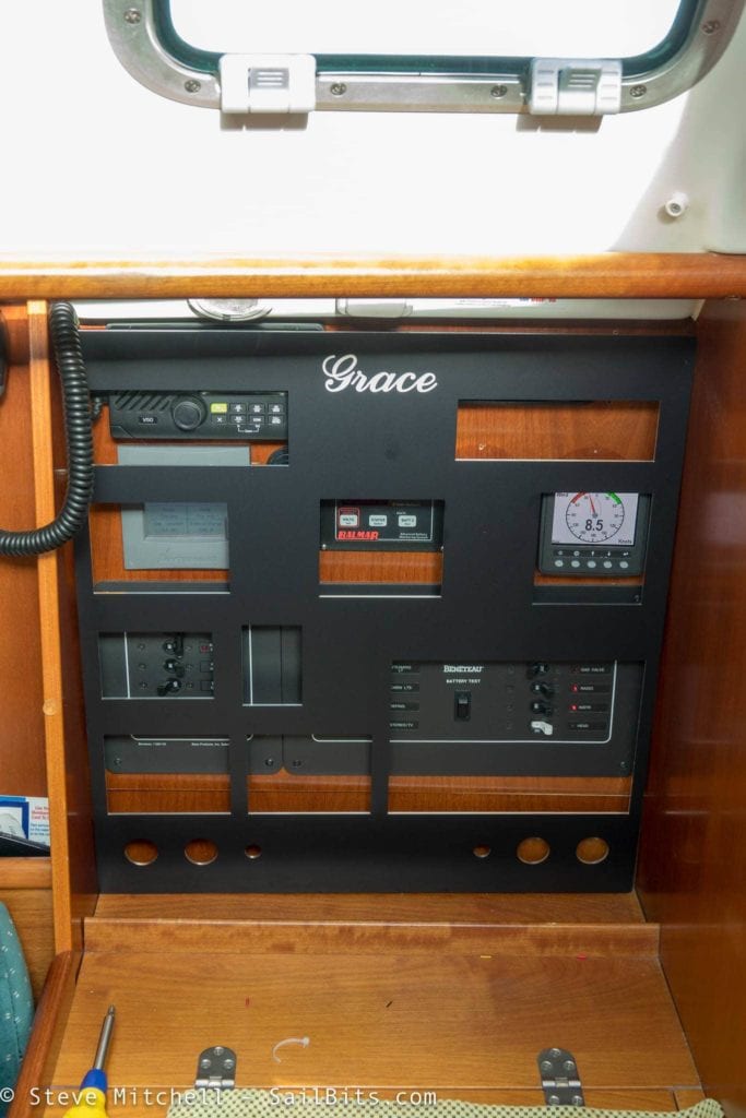
The first thing I needed to do was to test fit the new panel to make sure my tedious measurements were correct. I could see that I would have to shim the hinges on the bottom because the space, of course, was not exactly square or perfect, as I expected. But this was an easy thing to do.
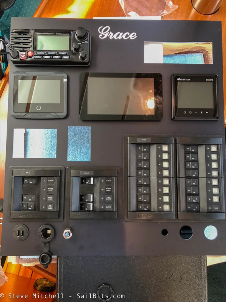
At this point I had verified that the basics were OK – the panel fit, I had all of the key pieces, and everything seemed to be within tolerances. I test fit everything I could to ensure the spaces were correct (they were) and to figure out other hardware I needed.
It’s important to note that if you design panel, make sure you:
Don’t trust manufacturer templates – get the real gear, measure it and compare it to their diagrams. Several times I found they were off by quite a bit, which with aluminum, can make for a messy fix.
Add 1-3mm for every opening – Depending on what the device is, add some slop so you can move things around to get items next door in line, and because aluminum is somewhat unforgiving. When I first used a panel like this, I made the hole exactly to the measurement, and the panel shaved off a ton of plastic from the radio I was trying to shove in, and left me no room for error.
I still needed to source screws, nuts, and a bunch of random other pieces such as primary wire and connectors. Off I went to the store to gather all of those items.
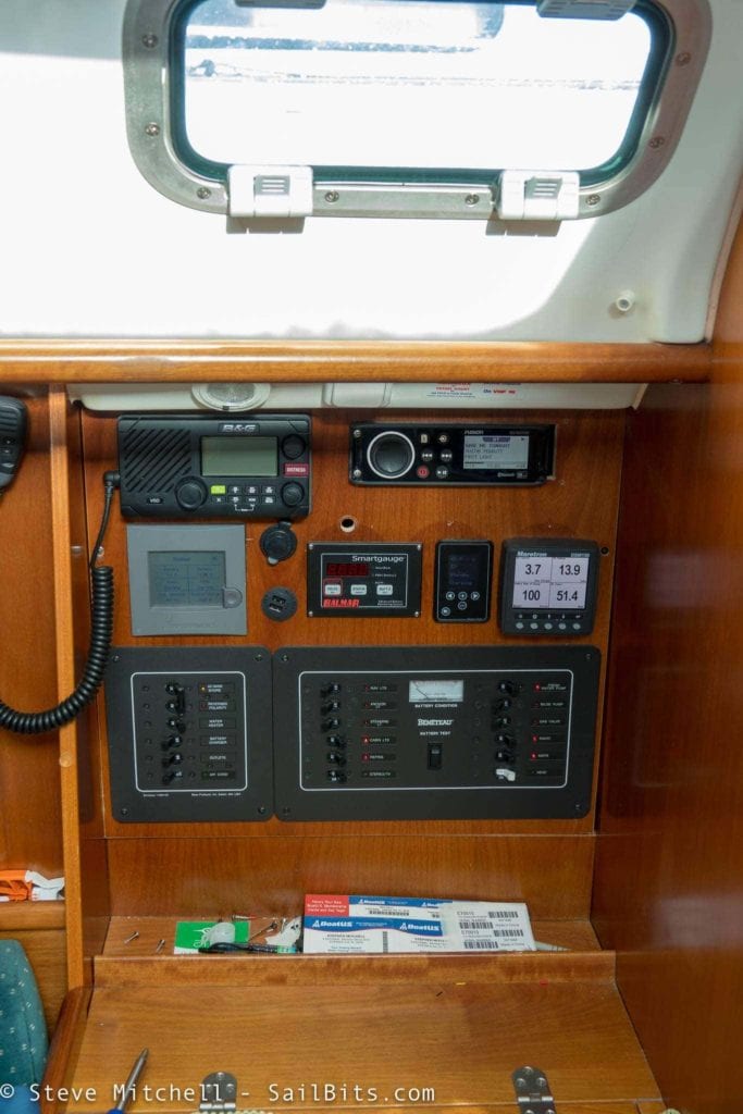
The next morning it was time for the old panel to come out.
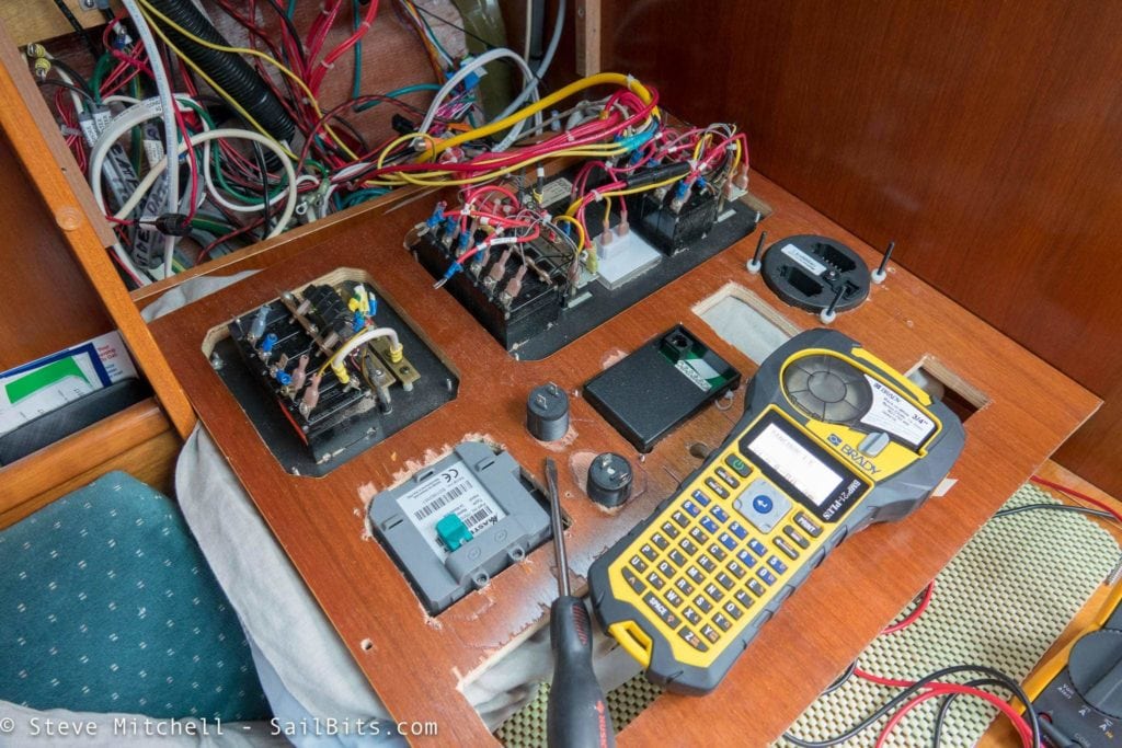
It was pretty cold in Seattle on the weekend I did this, so I started as early as I could to have more daylight. I disconnected the entire DC and AC system, and ran a 110VAC cable from the dock box into the boat for power tools and charging. My Wallas diesel heater comes off of a DC bus further up the line, so I used that to keep warm.
As I removed everything, I used my favorite Brady BMP label maker along with nylon cloth labels to make sure each item was clearly labeled for reconnection later. The nylon cloth labels are virtually indestructible and are one of my favorite things to have found years ago when rewiring Jammy.
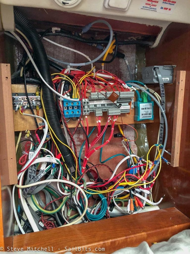
With the old panel gone, and most of the wires up and out of the way, it was time to remove the two blocks that held the old panel, remove the lower wood blank, clean up further down inside, and get the new panel mounted.
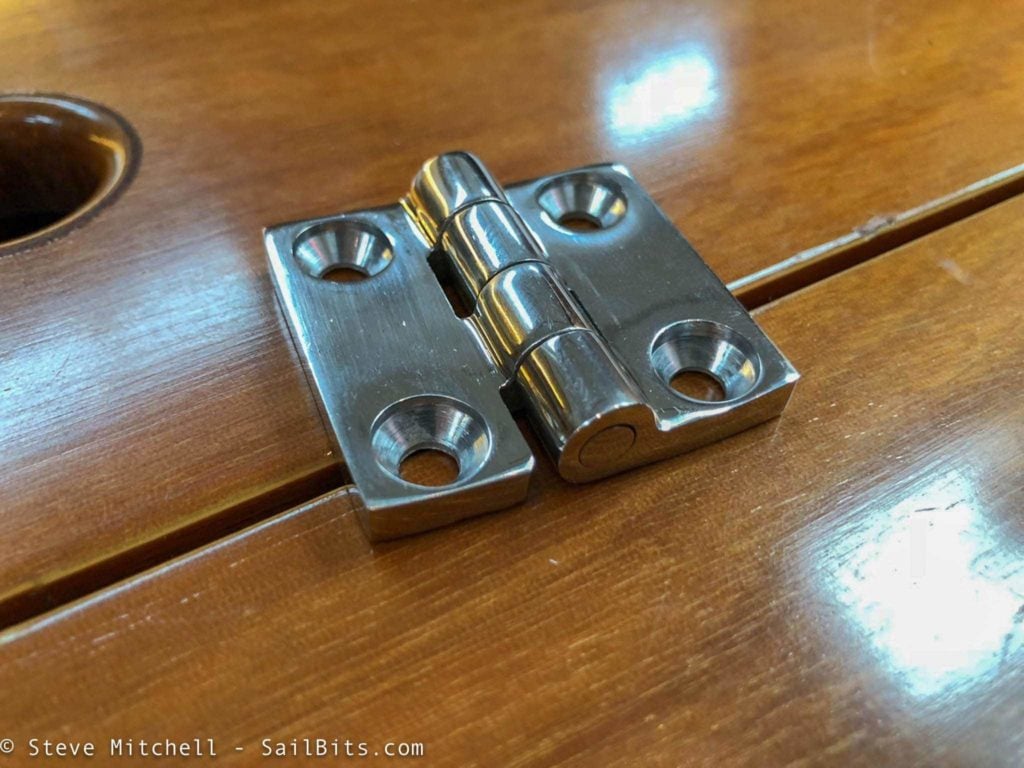
For the bottom edge of the panel, I used two beefy piano hinges that I had intended on using the standoffs on the back of the panel to mount to. They turned out to be far too small, so I was forced to drill holes through the bottom edge of the panel to mount these. That turned out to be a better solution overall since it allowed for some more fine tuned adjustments. I also had several of the standoffs come out of their mounting points, so it was good I did not rely on these to hold the bottom edge of the panel to the hinges.
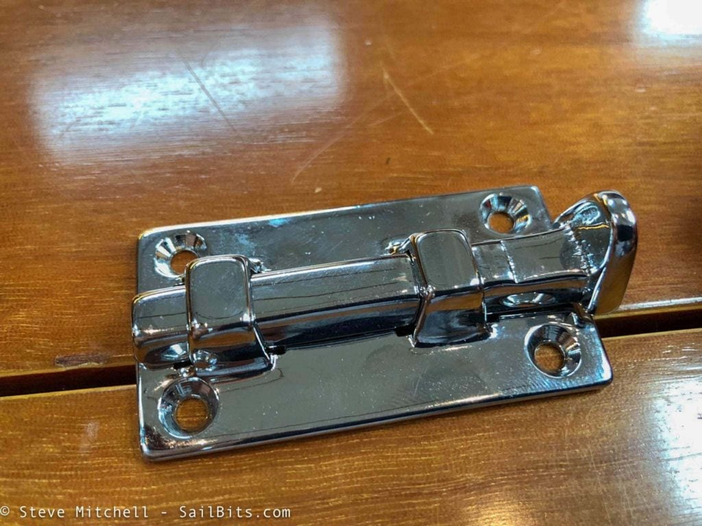
To hold the top edge of the panel secure while closed, I used what is called a boat bolt. Essentially it is a throw bolt with detents to hold it closed or open, and a copper spring behind it to keep it from rattling or making noise. I had done a panel a few years ago with a standard bolt, and it made a lot of a noise when things were bouncing around, so these seemed better. Each side of the panel would have one of these and they would slide into holes in either side of the wood near the panel.
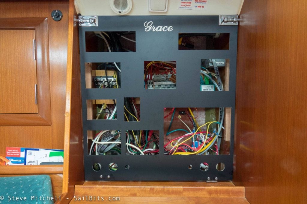
After a surprisingly short time, I had the panel mounted and secured completely. It swung easily when released, even though I did have to shim the right hand hinge to ensure a good fit. The top stopped right before the fiberglass structure above, and the bolts held everything securely.
One thing I was able to do was move the entire panel out almost 2 inches, giving me more room for the devices mounted in the panel, and the stuff behind it a little breathing room. The original panel had issues with the VHF radio (even the original radio) squishing its connectors up against the power blocks, which I didn’t like.
I also removed the 3.5″ wood spacer below the old panel, and took that space for more front panel space overall – quite a space gain in both height and depth!
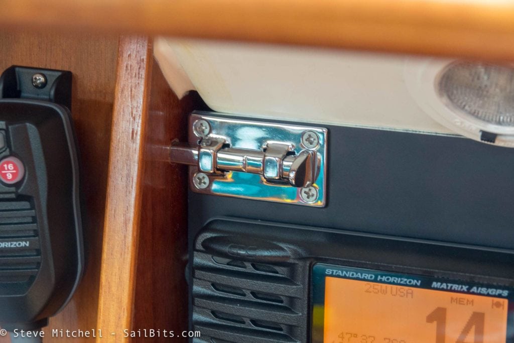
I really liked how secure the dual bolt locks were.
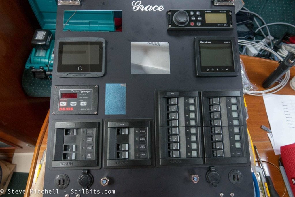
After a bit of trial and error, I determined that it would be far better to install everything I could while the panel was out on the table rather than one at a time while fully installed. I could reach everything easier this way.
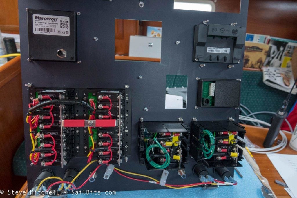
Other than some absurdly long bolts which I plan on swapping out, everything looked good and I even did some pre-wiring for things like the 12v and USB sockets.
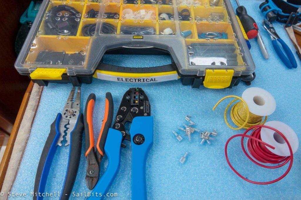
I had to purchase a new crimping tool as my old one fractured about a week before this project. After a bit of research I went with the higher end Ancor model and I am glad I did. I usually steer away from their stuff because some of the lower or West Marine branded versions are pretty crappy. This one has a ton of heft to it, and ratchets very nicely. Double crimps came out perfect for everything it touched. I also had my standby Stanley box full of everything I could need, and a good space for working. I knew I would have to run a bunch of new wiring, as well as fix and re-terminate much, if not all, of the existing stuff.
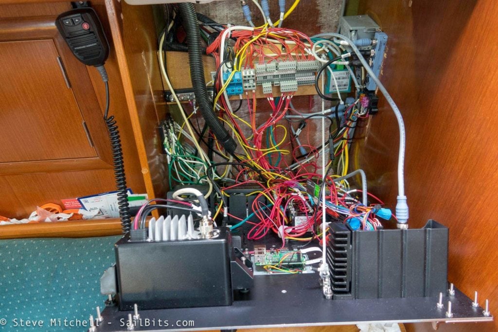
To hold the panel from tipping out too far, I used a length of Dyneema (non conductive is important!) and attached a pad eye to a mount point near the stereo, and another to the big wood crossbar holding the electrical distribution. It worked perfectly and allowed me to work on the panel without fear of it crashing open.
Note that the picture above is mid way through sorting and re-attaching all of the wiring.
At this point my back was the limiting factor – reaching over into that area became a strange form of torture over the next 2 days while I added new busses for the AC side, traced each cable from both AC and DC, re-terminated almost all of them, and ran them to their new destinations.
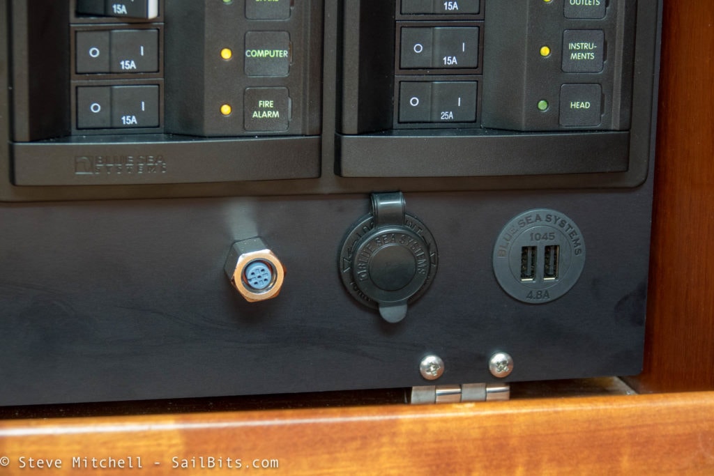
I thought about a lot of the usability aspects of the panel while I designed it. I placed the “dirty” stuff at the bottom that would likely have cables coming out. The USB chargers are used extensively while we are underway to keep all of the tablets and phones charged, as well as things like the Garmin inReach when we are at the dock or on anchor. Having NMEA 2000 is always nice, and I had that on my last panel too so I could connect a PC to do updates or diagnostics.
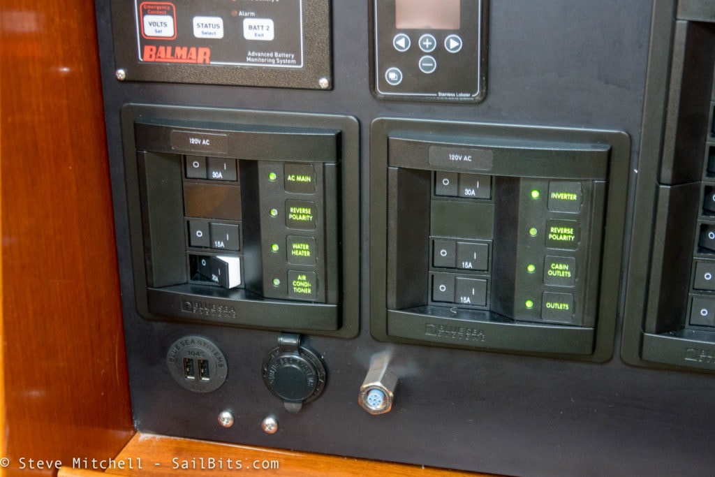
On the AC side, I finally had a properly wired and grounded set of panels. The one on the left is for the non-inverted AC power that the inverter passes through when we are connected to shore power, and runs the water heater and air conditioner. The one on the right is for inverted power which includes two circuits for starboard and port outlets. In the future I may use one of those for something else, since I never have that much on those outlets – I just separated them for now since I had the capacity.
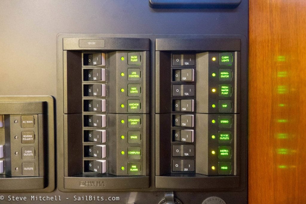
On the DC side, I ended up with 4 more circuits than I had with the original panel, and in a much more compact space. With the last panel, I had to combine some circuits for various things, such as my computer/internet alcove, and the CO2 and fire alarm. Here I was able to have all of the original circuits, plus the new ones I needed, and I still ended up with one spare for expansion.
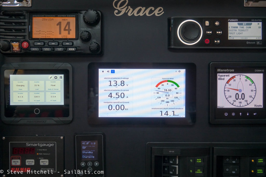
Further up the panel, everything else fit, and even more in line and true than I expected would happen. The radios, most commonly used, I put at the top and very visible. The previous panel was inset too much and created some problems when trying to use the stereo.
Critical instruments stripe the middle area with power management on the left, general data in the middle on the dedicated Raspberry Pi screen running SignalK, and marine stuff on the Maretron DSM 410.
More power stuff is right below with the Balmar SmartGauge and Fridge Optimizer.
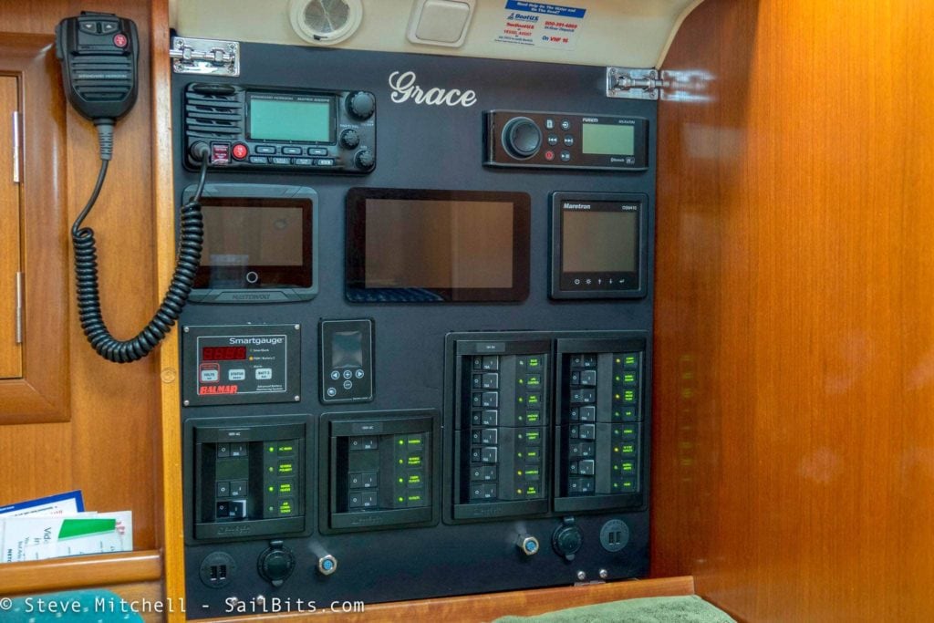
From the top down, left to right, here’s what is on the panel:
Standard Horizon GX2200 VHF radio, Fusion MSRA70N stereo, MasterVolt EasyView 5, Custom Raspberry Pi with 7″ touch screen, Maretron DSM 410, Balmar SmartGauge, Stainless Lobster Fridge Optimizer, AC and DC Panels, USB, 12V and NMEA 2000 outlets.
There is even some room for expansion at various key places on the panel. I am sure I will find something new to fill those spaces!
From the cost perspective, here is how things broke out:
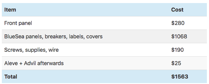
Note that I didn’t count the Ancor crimpers in this budget since I did not buy them specifically for this project – they’ll be used heavily for years to come!
Tips
Measure measure measure – getting a new panel to fit perfectly, especially in my case where I was moving it further out, required tons of measurements. I even mocked the entire size of the panel up in cardboard to make sure. Measuring the devices that go into the panel multiple times is also highly recommended.
Mock it up – create your panel in Front Panel Designer, but also go get the graphics for the actual devices and use OmniGraffle (Mac) or Visio (PC) to lay things out to see how it looks. I went through at least 30 revisions this way until finding the one I liked the most. Just because something fits somewhere doesn’t mean it should. Think about how you would use the various devices and how frequently.
Stand offs / rear mounted bolts – these aren’t really useful for an electrical panel. Three of them broke off due to the weight and torque from the wire. They aren’t seated very deeply – maybe this is something that I could have adjusted, but it was easier to use the bolts coming through that are holding the devices as points to tie down cables.
Leave room – aluminum is hard to work with without creating a mess. Leave some space around each device (1-3mm depending on the device) so you can get them in.
Drill afterwards – I’ve tried to get the mounting holes just perfect in previous panels, and have Front Panel Express drill them for me. This works for some things but also limits you. Being able to test fit everything and move things around a few millimeters and then choose your drilling location is easier in my opinion.
Protect your workspace – this is a no brainer for most folks, but when you drill aluminum it leaves very sharp shards everywhere. I put down a lot of protectant everywhere in my work area, even the floor that I was walking around on because it tracks easily.
Test fit everything – the panel in the hole, the devices in their spots, and make sure you have provisions for shims and spacers if needed. Test it over and over until you’re sure it is right.
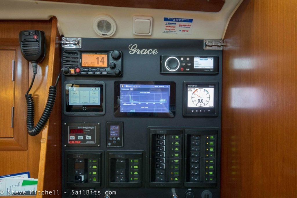
Taking pictures of dark black panels with shiny and sometimes bright displays on them is pretty hard. I’m a pretty decent photographer, but this was one of the hardest things I’ve ever photographed.
Nevertheless, the panel looks a lot more impressive in person that it does in the pictures, and I absolutely love the upgrade. I have more space, a much safer AC power system, more expansion and room to grow with both AC and DC power, and the overall solution is far more usable in general.

