I have wanted to update my VHF antennas for a while, specifically to get a dedicated AIS antenna for my Class B transponder. I decided to move forward with this project this winter.
Rendezvous came with two Shakespeare VHF antennas which were connected to a radio each in the salon and on the flybridge. I added a Vesper VHF / AIS splitter and various AIS Class B transponders, depending on what I was testing. I added this splitter to the salon VHF as I used it the least.
The existing antennas were OK outside, but the ends at the radios were in bad condition. They had poorly crimped ends, and exposed wiring. The outside cabling was also wearing where it came out of thru hull openings and had exposed cabling. After finding these when I bought Rendezvous, I replaced them with the same ends that I used on Grace and documented in Proper VHF ends are easier than you think, but I wanted a higher quality solution.
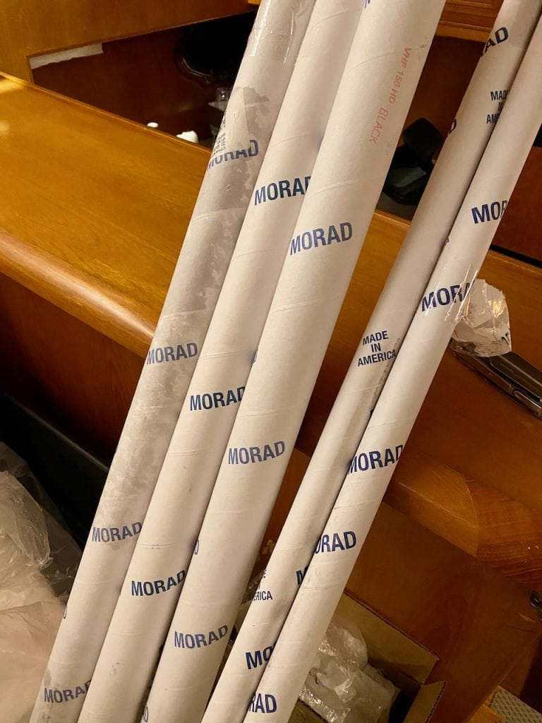
In looking for replacement antennas, I immediately thought of Morad. Several friends and the folks over at Slowboat have recommended them, and I’ve always wanted, if the chance arrived, to have them myself. After some emails exchanged with Morad, I had my parts list and placed the order.
Equipment List
VHF Antennas
- 2x VHF antennas – black anodized
- 2x V5 5′ stanchion – black anodized
- 2x M87 – Stanchion/Thread Adapter – black anodized
- 1x M6 – 1 inch diameter Bulkhead Mounts (pair)
- 2x M6B – Spacer Block
- 2x 25′ coax VHF cable
AIS Antenna
- 1x 162MHz AIS tuned antenna – black anodized
- 1x V2 – 2 ft. Stanchion – black anodized
- 1x M88R – round flange mount
- 1x 25′ coax VHF cable
Design
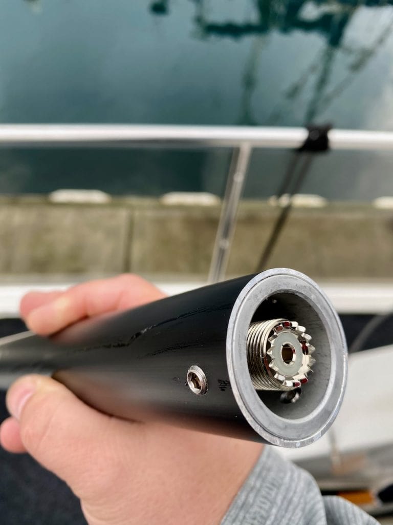
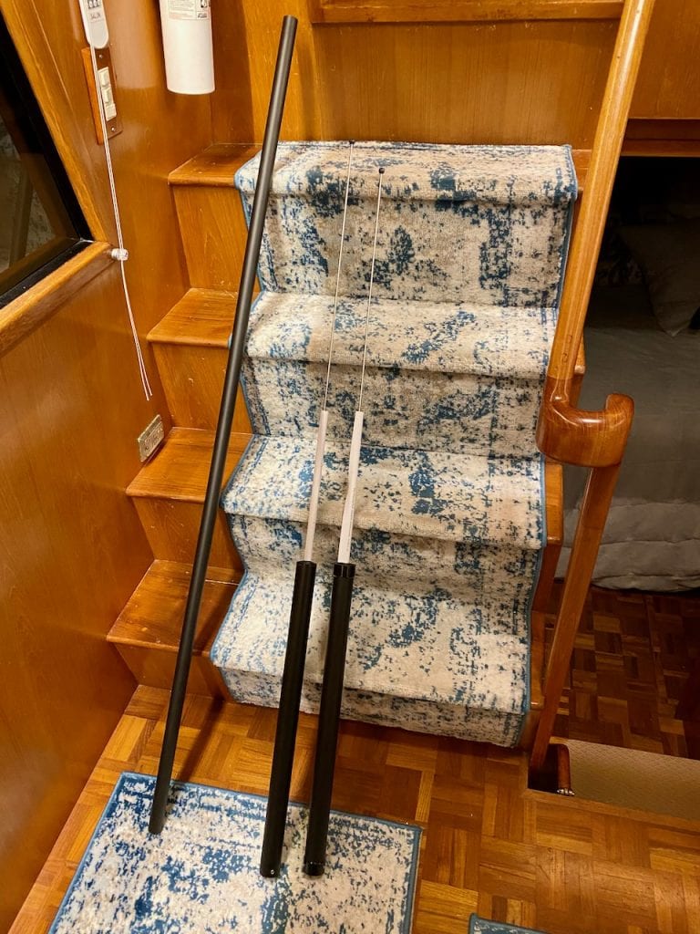
Morad uses a nice design that allows for various different mounting options and combinations. One of the best parts of this modularity is how the cable connects to the antenna itself. Instead of having to figure out how to reverse turn the cable, or do other scary things to a brand new antenna, the bottom of the antenna has a female connection, and allows you to screw the connector on, and then use hex wrenches to attach it to a mounting point. It seems small, and other vendors provide similar solutions, but Morad’s full set of equipment has this across all of the antennas and mounts.
I chose black anodized versions of the antennas and components based on feedback from a friend who had a white version have flaking issues with the paint. The black, being anodized, won’t have that issue. I did have to be a bit more careful not to scratch them while installing. It also had a side effect of matching my flybridge canvas and sort of disappearing.
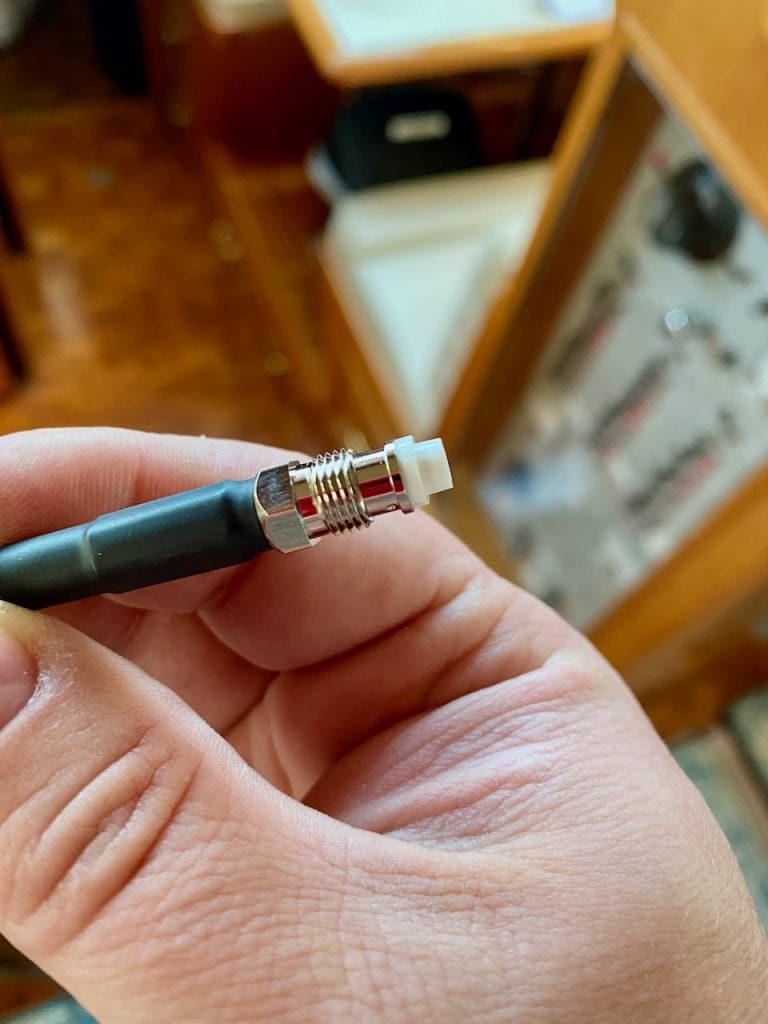
Their VHF coax cabling is also well thought out. One end is the standard PL-259 connector, while the other is a much smaller connector, allowing you to pull it through small holes and locations without compromising the factory end.
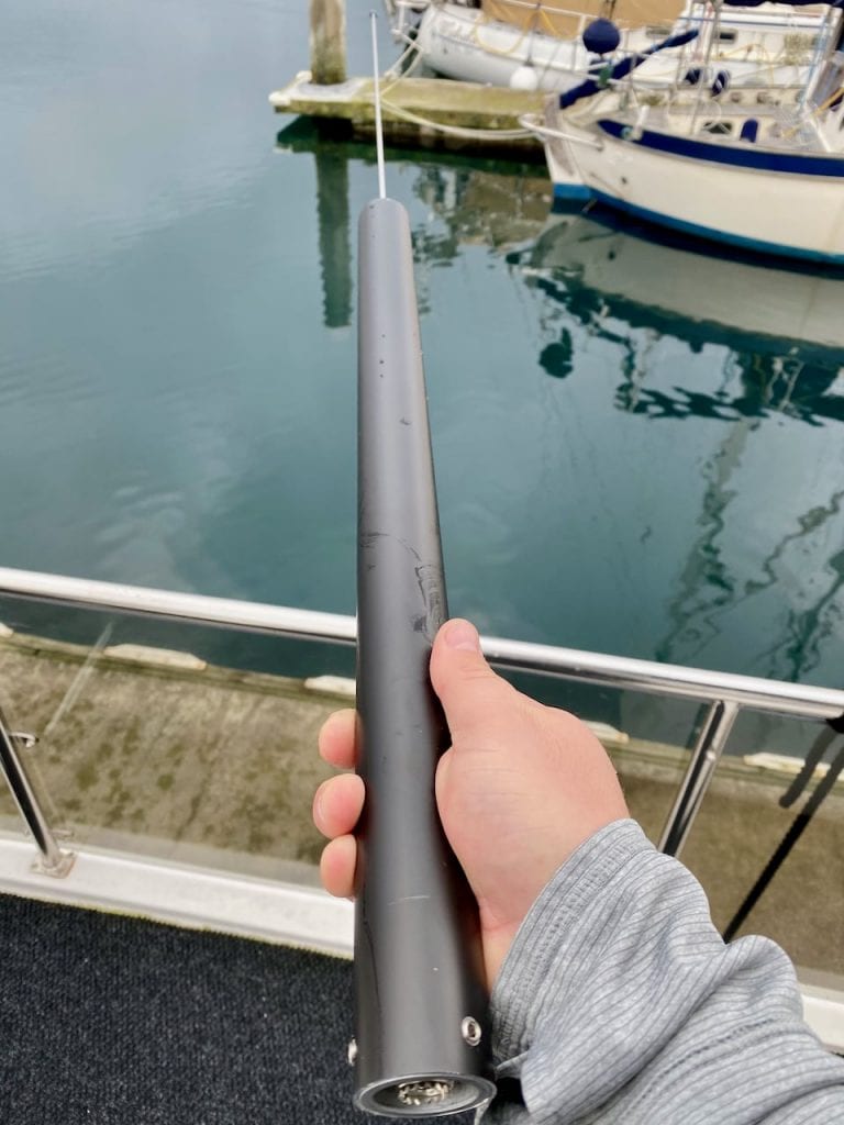
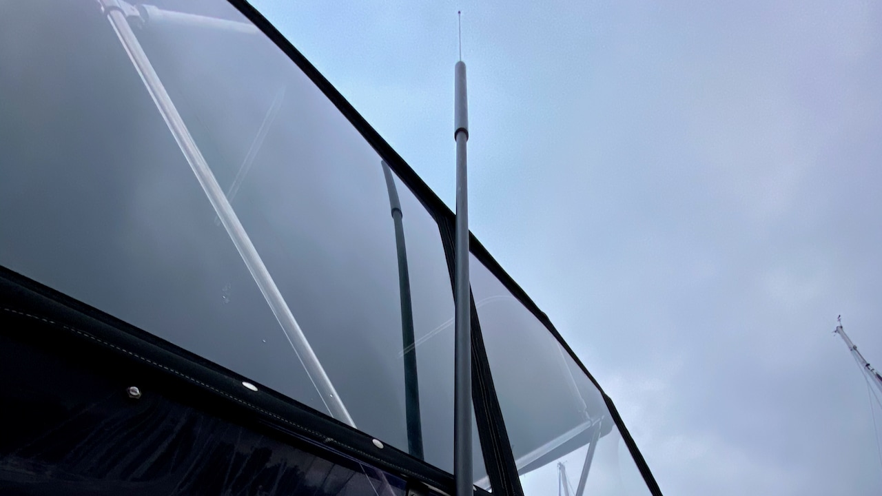
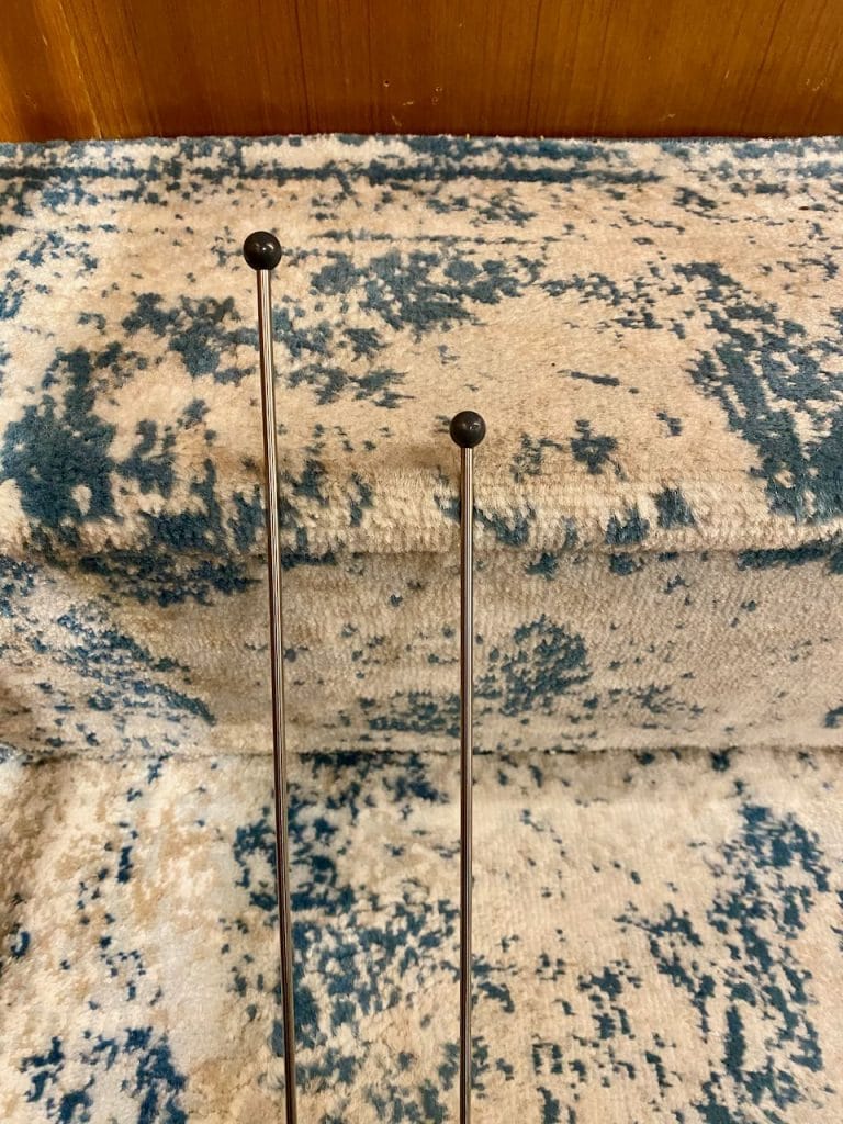
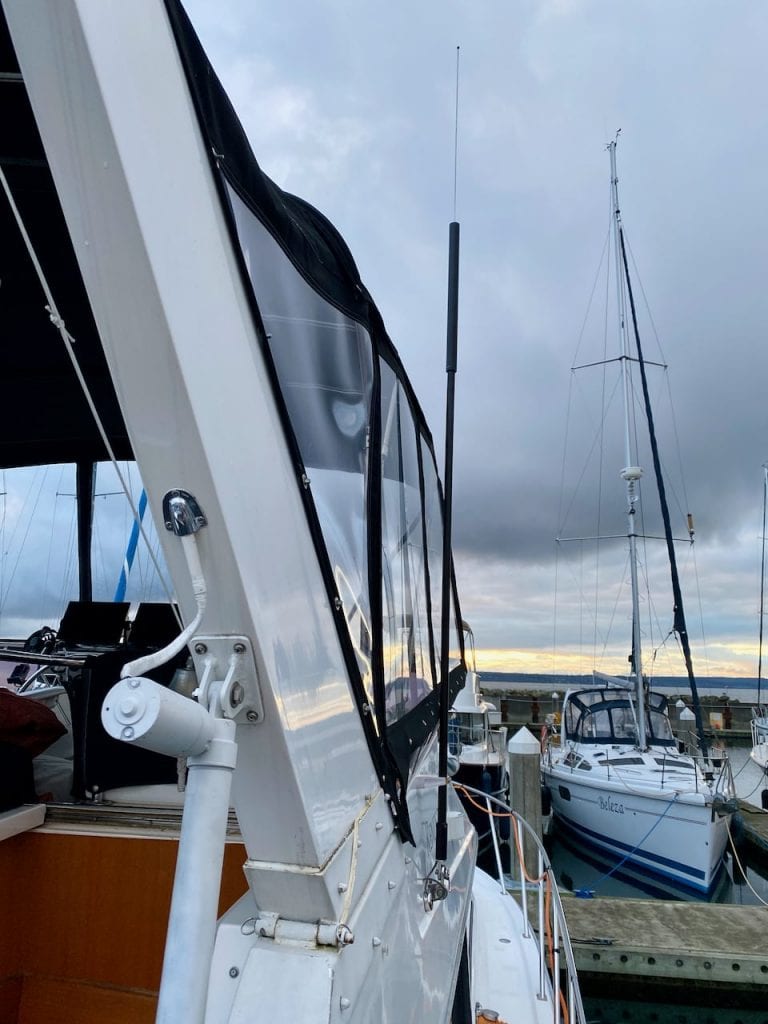
Morad’s VHF antennas are easy to spot most of the time. They have a much larger aluminum lower body with a small thin whip for the top portion of the antenna. With my new design, I was adding at least 1 foot to the overall height, yet I ended up with about the same (or less) weight, and less windage at the top as a result of the smaller whip.
Cable Glands
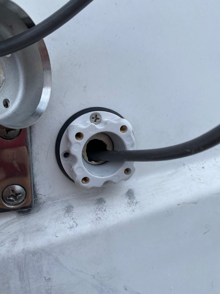
Part of the reason the cables on the old antennas failed was the cable glands from the outside into the flybridge void areas. They had some sort of screw down compression rings, and very little rubber between the cable and the stainless steel ring, and they had rubbed through the outer jacket of the VHF cable.
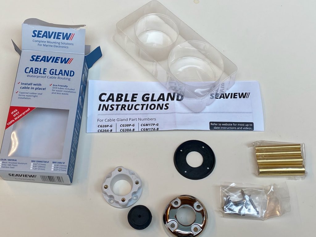
I chose to use Seaview stainless steel cable glands, which were quite a bit bigger than the old ones, but would provide a lot better seal and protection.
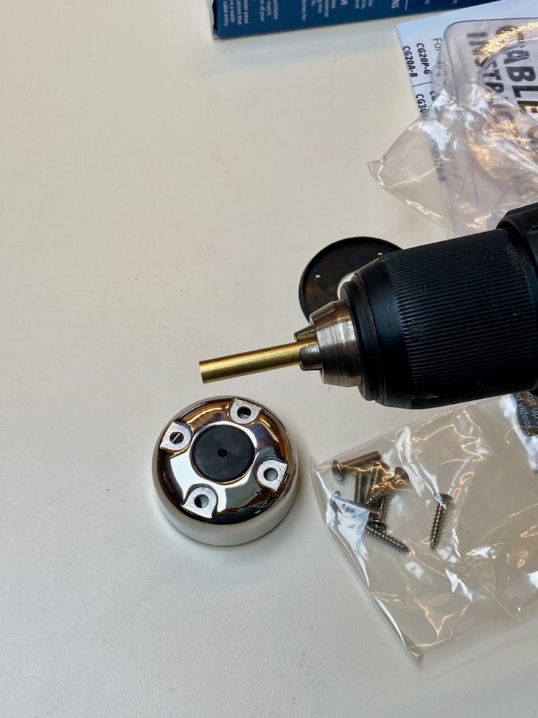
One of the coolest ideas I’ve seen in a while, Seaview includes a set of copper tubes that you can use in a drill to cut the hole in the rubber plug that goes in the gland. I have put a lot of cable glands on my boats, given the amount of antennas, cables, and other things I run outside. Trying to drill a hole in one of these plugs is not only frustrating, but downright dangerous. Even when you have it in the mount, securely screwed down to a board, it still binds on the drill bit quite a bit.
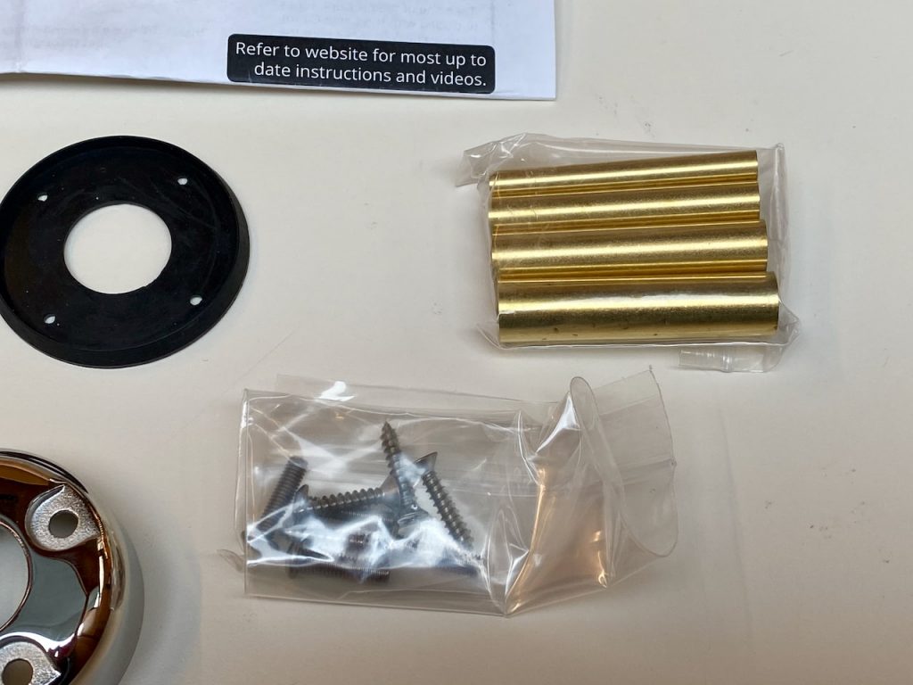
The copper tubes are sharp, and cut through the rubber very easily and quickly. There are a number of sizes that come with the gland, allowing you to pick the perfect size for the cable you’re running through.
Installation
Installation was pretty straightforwards. The VHF antennas went on to the existing mounts, but with an additional upper mounts for strength. I ran the new VHF cables which was the hardest part since one pulled apart, and required some work with a cable tape. The smaller ends made a huge difference in pulling the cables.
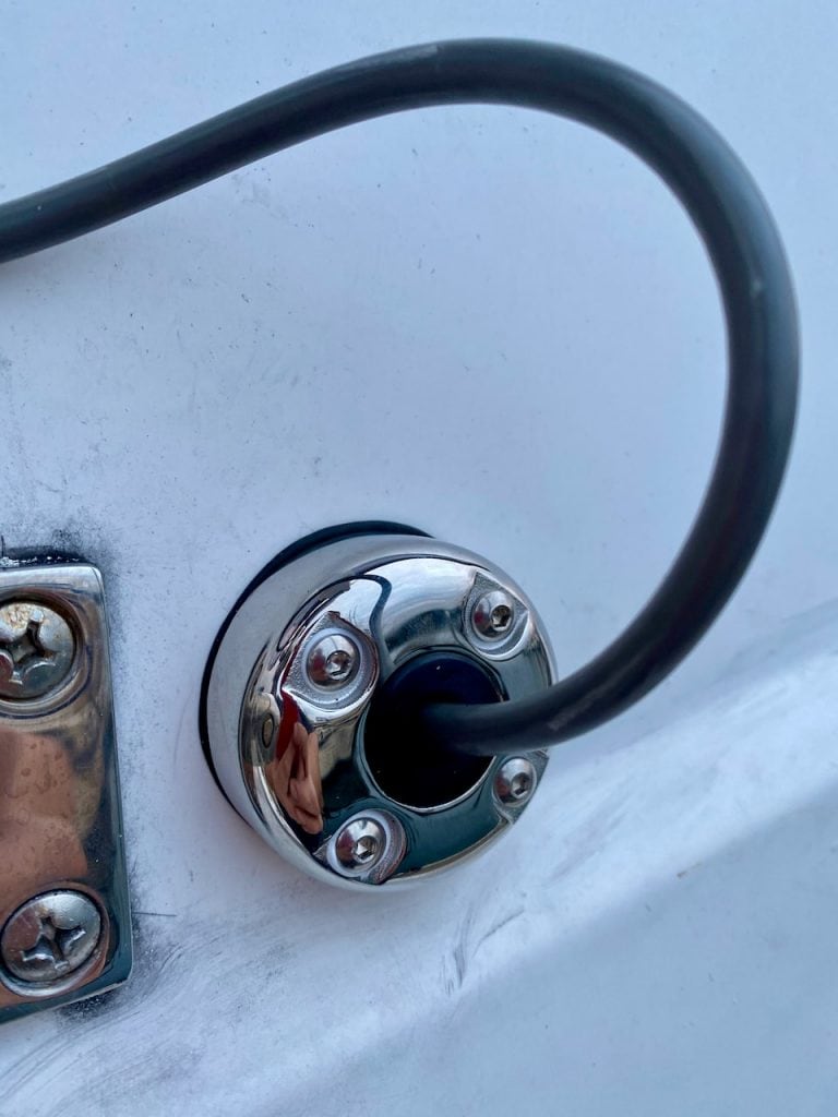
The Seaview glands were pretty easy to install after getting the right size hole in the rubber plug. They look a lot sharper than the original ones, and are far more securely connected to the boat with the plastic base and then upper stainless collar. They’re also much better at keeping the cable secure and the whole setup waterproof.
I followed Morad’s instructions and used silicone grease wherever there were joints, and used the hex keys to tighten everything down nice and snug.
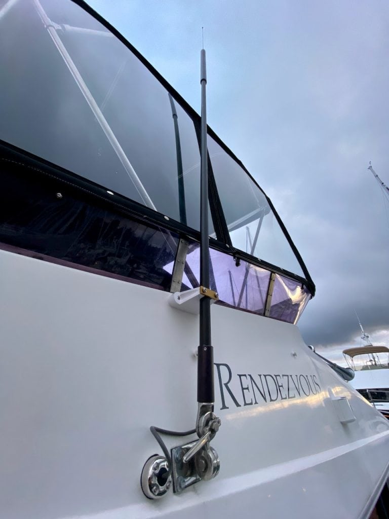
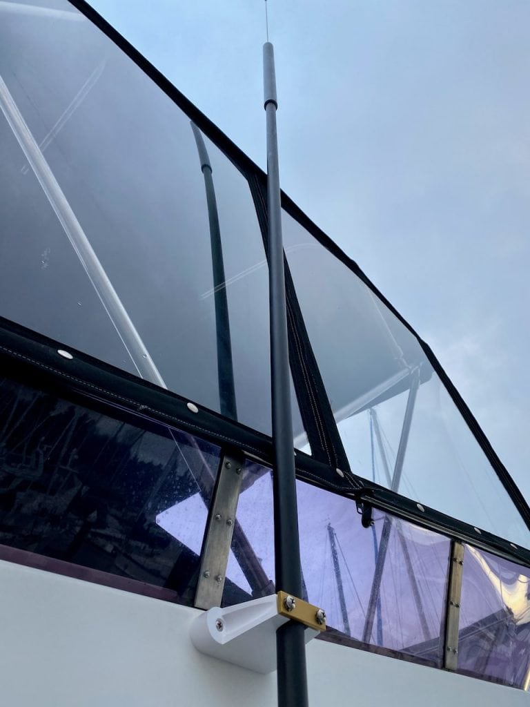
I chose to add a bulkhead mount above the existing ratchet mount to provide for additional stability and strength. This area of the flybridge has no access to the back of the mount or general area. I would have rather replaced the entire mount with a beefier system, but there was no way to do that without cutting huge holes inside and somehow patching them.
Both VHF antennas are far more stable and secure than they were before, have brand new cables and antennas, yet are still able to be folded down if needed.
The AIS antenna required a new mount on the arch, and a new cable run down to the flybridge equipment area. I also moved the AIS transponder up to the flybridge, and removed the VHF splitter from the salon.
So far, I have seen a dramatic difference in both my Furuno VHF in the flybridge, and the Standard Horizon VHF in the salon. Not only can I hear more in general, but it is clearer and easier to understand. I’ve done some test calls with friends, and they are able to hear me very well.
AIS was more measurable since I am a base station and transmit my data to various services online. By switching to a correctly tuned AIS antenna with a better cable and eliminating the splitter, I saw an increase from around 110 to 195 vessels being “seen” and tracked. That’s almost double the coverage. Of course, most of those vessels are probably further away, which would not matter as much for avoidance, but as a base station, it improves what I can see of course. I’ve noticed I can now see vessels in Lake Washington and much further south/north than ever before. This data was gathered with the boat sitting at my home marina.
This upgrade has already helped in the few trips I’ve been on – much clearer conversations on VTS channel 14 between all the ferries and ships, and much more AIS targets while underway. I’m glad I was able to get this project done this winter!
Archived Comments
These are read only comments from the old system. Scroll down to participate in SeaBits Discussions, our new interactive forum attached to each article.
Chris
April 14, 2020 at 8:25 pm
Hi Steve,
I’m about to do an electrical refit on my boat. I was planning to run 2 Shakespear 5230 (14ft) antennas. I have 2 Icom M506 radios. One of the antennas will have a splitter on it for the Garmin AIS module and VHF. Do you think there could be potential performance degradation by splitting it?
Thanks,
Chris
M/V Brigadoon
Chris
April 15, 2020 at 2:29 pm
Hi Steve,
The AIS is a black box unit from Garmin: https://buy.garmin.com/en-US/US/p/623924 and has a powered splitter built into it. I elected to go with a standalone AIS box vs a VHF radio with a built in unit as i’ve had issues with them on my previous sail boat. The guy helping me install these said there was little signal degradation but wanted to get your take on it.
Chris
M/V Brigadoon
- Steve Mitchell
April 15, 2020 at 5:42 pm
I don’t see in the specs for that unit where it says it is a powered splitter, or offers amplification, but that could be hidden elsewhere. Nevertheless, this should not add much in terms of signal loss. You have a second radio anyhow which will be directly cabled, so in sketchy areas of coverage, you could always use that one.
If possible consider putting the AIS unit/splitter on the least used location/radio.
Rob
July 8, 2020 at 4:38 pm
Hey Steve, I actually work for Morad and thought you might light to know that your friend is probably mistaken regarding the flaking of the white antennas (unless he seriously scratched one and a long period of time took its toll). He’s probably referring to a white power coated adapter since powder coating can flake from straight current.