My soldering skills are marginal at best, and as a result I have used crimp-on VHF ends for the last 10+ years. While not wanting to admit this, I finally was chatting with some radio-savvy friends of mine, and they were aghast that I had even considered using one of these abominations. So I set out to learn a better alternative without having to be a world-class solderer, or have someone do it for me.
I’ve learned from years of using VHF radios that the whole system has to be in good condition for the thing to work well. You can have a really fancy radio, but a crap antenna, and be frustrated that performance or quality suffers. Same goes for the cabling from the radio to the antenna itself.
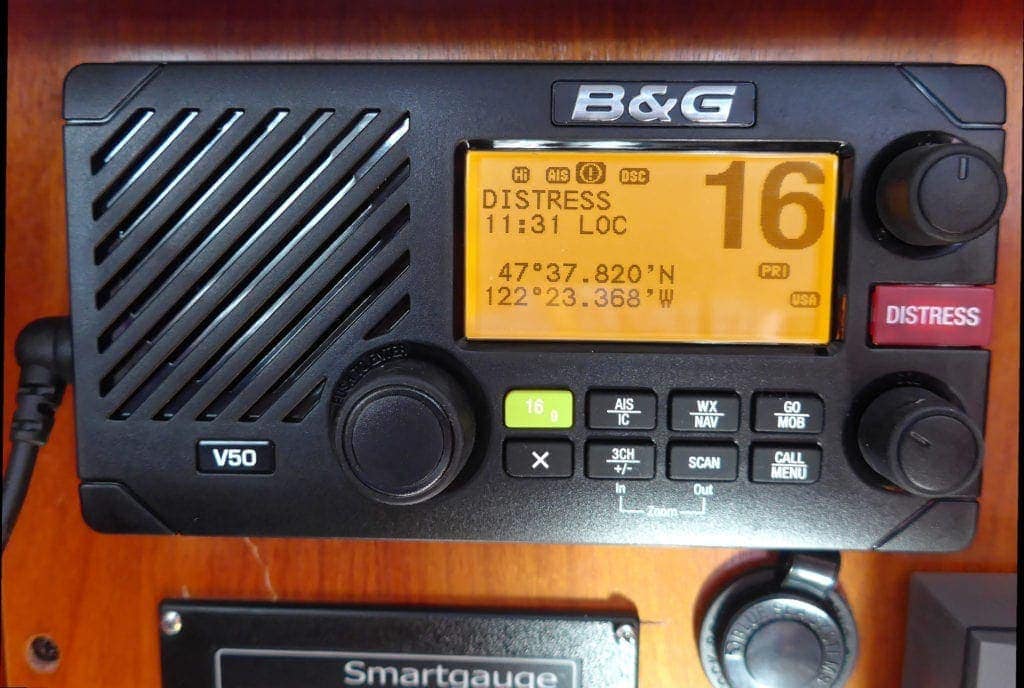
B&G V50 VHF radio
When I bought Grace, I removed the really old, non-DSC radio that she came with, and replaced it with a B&G V50 which I wrote about a year or so ago. I still like the radio, but had been having some performance issues in the last 6 months that I had traced down to either the cable or the antenna.
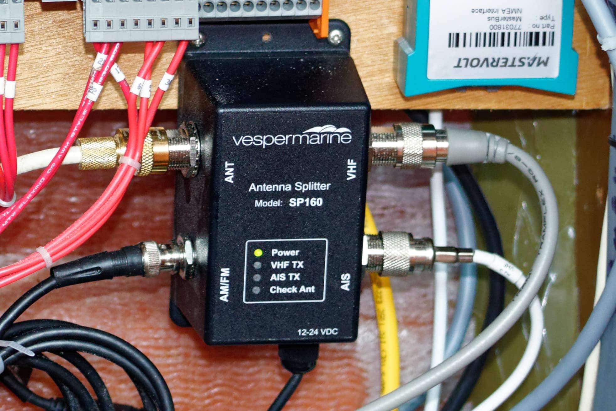
Part of the system I installed with the B&G V50 was a Vesper AIS splitter, which I had to do as I did not have a dedicated AIS antenna nor place to install one. I am not a fan of using splitters on the primary radio as it adds loss and complexity to something you rely on for emergencies. Splitters require power, and have more parts and pieces, which is something I try to avoid on critical systems. However, I didn’t have an option at the time, and it served me well. Part of another project I just completed was to install a dedicated AIS antenna on a radar mast, which I will have an article on soon, so the splitter was removed as part of this VHF tuning/troubleshooting.
The other area I checked was the VHF cable itself. I had replaced a falling-apart connector at the radio with one of the crimp on Shakespeare PL-259-CP-G connectors. I had used these on Jammy and other boats, and they seemed to work OK, plus they were quick and easy to install. However, I knew that a real soldered connection was probably a better choice.
One of the other trouble spots on sailboats is where the cable goes from inside the cabin area to the deck, and then into the mast. On some boats there is a connector there that can be very poorly designed or simply degraded because of the location and connectors. I traced the cable from the nav station to the deck fitting, and can’t find any connectors or breaks in the cable. On one hand, this is good, because there is a contiguous cable from the radio to the antenna. On the other hand, if the mast ever has to come down, I suspect I will be disappointed at having to cut this cable and splice it back together later.
Ok, so thus far I have a good (new) radio, a decent (some would disagree) end at the radio, and what looks like a contiguous cable to the mast. Time to check out the antenna as best as I can….
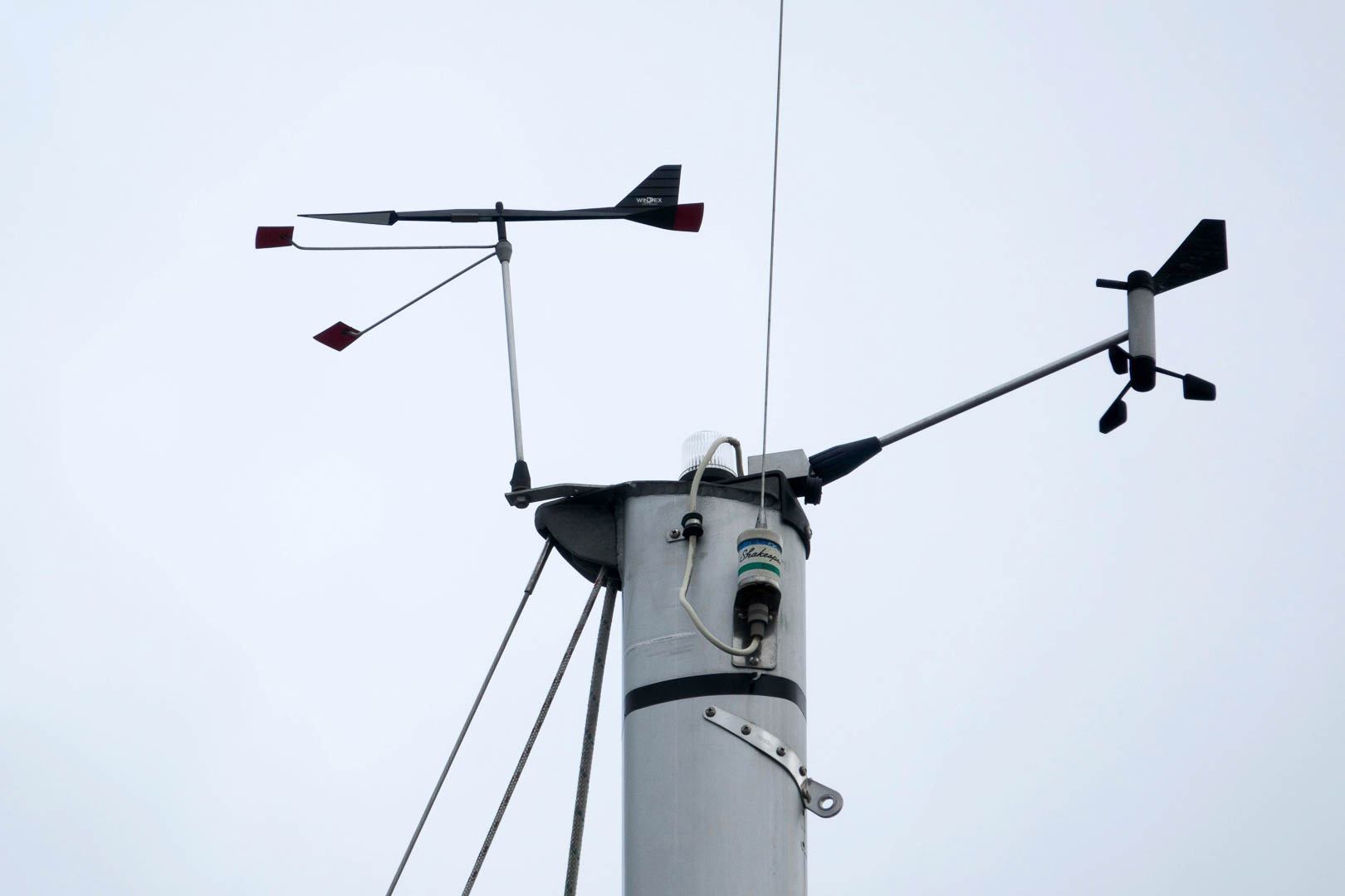
Grace’s masthead instruments
Since I am afraid of heights, there was only one way for me to check on the antenna easily – break out the Sony RX10 mkIII 600mm zoom camera and walk down the dock! I am still impressed daily with this camera’s ability to take steady, handheld pictures at crazy ranges. At first glance, the antenna looks to be in OK condition, and the connectors don’t look messed up. It also looks like the same cable that I can see at the base of the mast and inside at the nav station.
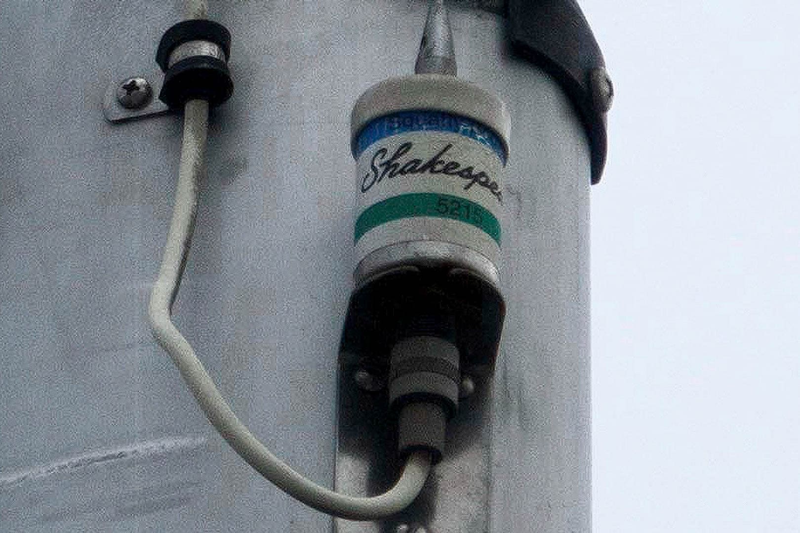
Zoomed in on the antenna and connectors
Zooming in on the image itself, and I can see what appears to be a good end and no other damage. The Shakespeare 5125 squatty body antenna is identical to the one I had installed on Jammy a few years ago, and is what I would choose now as well if I had to replace one. Nothing else looks out of the ordinary, but of course an in-person inspection of the ends and such would be a better idea.
After chatting with some friends about the various issues I was having, they all agreed that my crappy, crimp-on connector was not doing me any favors. So I set out to replace it. A few internet searches later, and I landed on one of my favorite sites – Compass Marine’s MarineHowTo.com written by Rod “RC” Collins. I’ve used this site to learn about so many things – from batteries to charging to instrumentation to you-name-it.
The page that was my savior is Easy VHF Terminations and it had everything I needed to know about fixing my crimp-on ends. In fact, RC has examples of why not to use the crimp-on ends in rather dramatic pictures.
The best part of MarineHowTo.com is that RC tries to write about things in a way an average boater could understand and work on. In this particular article, he takes great pains to use tools that most boaters would have at hand, not fancy, expensive, and rather dangerous AC soldering irons with short cords, etc.
After reading his article several times, I ended up purchasing a few things:
- MPD Digital RG8X-PL259 UHF Male Crimp Connectors
- Rosin Core Solder
- Dremel 2200-01 Versa Flame Multi-Function Butane Torch
The first two items are fairly obvious – ends for the cable, and solder. The third is a fairly inexpensive tool that I chose to purchase that replaced another tool I always have on the boat – a torch. I have fallen in love with the Dremel Versa Flame – prior to this I would always have a small torch that had an attachment to allow me to heat shrink wrap for electrical wiring, which I do a lot of. The Dremel has this, as well as a soldering tip, and a few other attachments that make it a true multi-tool.
I already had a crimping tool which had inserts for the PL-259 ends, so I was ready to follow RC’s article. It was super easy, and I ended up with an end that I think is far better connectivity-wise than the crimped one, although I am sure it is not perfect!
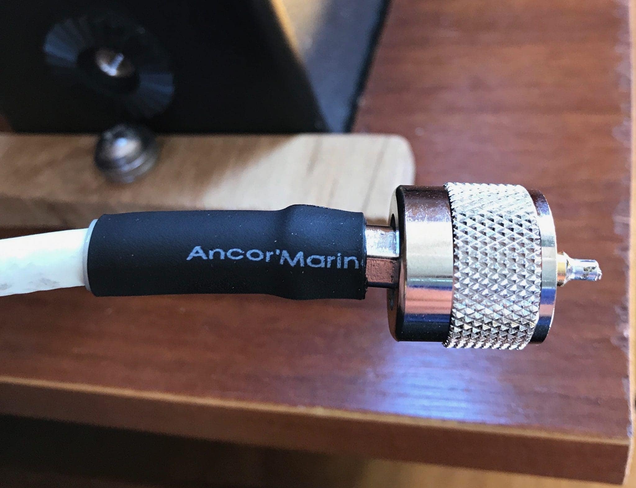
VHF PL-259 completed end
In the picture above you can see the end and protective shrink wrap, along with solder left over on the tip that I removed post picture taking. The whole affair took me about 10 minutes the first time, and with RC’s article was very easy to understand. Cutting the cable carefully with my multi-tool, flaring the shield back, covering and crimping the back end – all straightforwards. The Dremel soldering attachment helped me get plenty of solder down the tip to ensure a good connection. Switch to the diffuser on the Dremel, and the heat shrink is done and in place in a handful of seconds.
It was so easy I decided to re-do the crimped-on connector for my Vesper XB-8000 AIS unit and new antenna.
After making these changes, I have noticed an improvement in VHF radio traffic on the B&G just from listening to the local Seattle Vessel Traffic Services (VTS) on channel 14 while on the boat doing projects. Prior to the change, I wouldn’t be able to hear all of the ships and ferries clearly, and even the Coast Guard VTS folks would come in spotty sometimes. After a week of observations, I can already say that it has made a difference which should improve overall quality in using the VHF radio.
The AIS change was even more dramatic – prior to a week or so ago, I used the mast-mounted VHF antenna with the splitter I covered above and my Vesper AIS unit to send AIS data to various services online which I have covered on my Services page. I even setup a proxy / data reduction system that I wrote about last year to help save on bandwidth usage.
After disconnecting the splitter, I installed a dedicated AIS antenna on a 9′ high stern-mounted pole, and expected my coverage and range to decrease because of how low it was now, and all the interference in the marina at that level. It did go down quite dramatically until I re-did the VHF connector. Now, it is back up to the same levels as you can see on my station at MarineTraffic.com. I know that the connector was not the only reason, but it sure made a big difference.
I always considered properly soldered ends to be something only ham radio guys could do, and even then it took years of practice and fancy tools that I would only use very infrequently on the boat. Thanks to RC’s great article, I know I can do a much better connector than the crimp-on ones, and get a far better connection with a reasonable investment of time and tools I already had on board. It was also the only way I could safely put an end on a remote cable for the AIS system – trying to handle an AC-based soldering iron in close quarters in the lazarette would have been a nightmare.
I highly recommend every boater checks their VHF radio cabling once a year, and especially if you have an older boat, invest in both newer/thicker/less loss cable and proper ends. It’s made a difference for me, and I learned something new!